#EggsAndDarts
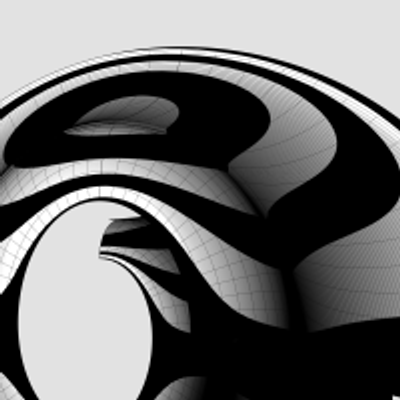
To transfer the egg and dart in https://pixelfed.social/p/Splines/797038670230603707 to the #doublyCurved surface of an #ovolo is a multistep process.
There are 24 eggs and darts around the entire Ovolo. So each egg and dart nominally occupies 360°/24 = 15°.
#Revolve arc AD in https://pixelfed.social/p/Splines/792124787573855518 about the #columnAxis to get the virtual surface. Points A and D are same in both figures. Then use cutting planes as described in https://pixelfed.social/p/Splines/790645054230337543 to get a wedge-shaped segment whose angle is 15° and one side of which is marked with A and D.
This is a doubly curved surface. Unlike a cylinder, where one side is straight while the other is curved, the surface of an Ovolo is curved in both horizontal and vertical directions.
To transfer the egg and dart to a doubly curved surface, we need a new operation called #UnrollSurface, which unrolls the wedge shape into a flat surface whose top-left corner is marked Q. Note the top is wider than the bottom.
Place the flattened wedge between the rim and the flat slab and align the top of the flat portion of the slab with the center of the top edge of the flattened wedge. Temporarily move the dart to align its center too, but only move it in the horizontal direction
If the flattened wedge were flexible and if the eggs and darts were flexible, we could flip all of these over, flex and squeeze the solid shapes, and line up Q with D so that the rim and dart appear "outside" the original wedge while the slab remains "inside" (or toward the center of the Ovolo).
Fortunately, in a #CAD tools, solids don't always have to be treated as rigid. Now we will use another new operation called #FlowOnSurface to flow the egg and dart on the wedge.
We then slice off the top of the egg and dart at the location PQ in https://pixelfed.social/p/Splines/796958366767133979.
Finally, we separate the dart, which we had aligned with the egg to minimize distortion
#columnAxis

#Ovolo #TectonicSurfaces for #EggsAndDarts
Continuation of https://pixelfed.social/p/Splines/796857354690493749
Reconcile this figure with the figure in https://pixelfed.social/p/Splines/792124787573855518. The points A, B, C, and D are the same in both. The arc from A to D is the profile for the invisible virtual surface that encloses the decorative elements. Arc BC is start of the #tectonic surface where decorative elements rest. Points K, L, M, P, and Q are new here.
Point K is the center of the Ovolo and lies on the #columnAxis. KD is the upper radius of the Ovolo including the decorative elements, and its length is 22 parts of 176.
The horizontal distance between C and D is 1 part (8 units), and the vertical distance between C and P is also the same. PQ is where the eggs and darts are sliced off exposing the wall CP around the entire Ovolo and making it visible.
Normally, the decorative elements rest on the surface swept by arc BCP. In the case of https://pixelfed.social/p/Splines/796786779066451143, we have a fully round egg shape half of which is buried behind the arc AQD. In the concave variant, this means part of the tectonic surface is also carved out.
In other words, instead of limiting ourself to the range CD (or PQ), we are taking liberty to gouge out portions as far back as arc LM, and that's OK. Neither #Vignola nor #Scarlata mention tectonic surfaces or how far back they should or would be. The actual depth will depend on the choice of our decorative elements — in this case, concave eggs that are fully round like natural eggs.
The concave version of the egg is shown on the bottom right and it lines up with the orange wireframe with the round hole on top. The wireframe of the convex egg is superimposed on the concave portion to show where it will be placed if both are used together.
The depth of the dart slab is the same as that of the concave egg. The slab of the convex egg is thinner because we have to leave room for the bulge of the egg.

Classic #IonicCapital #Tectonic Surfaces Plan
We already made the 8 unit tall #fillet at the bottom of the #capital a part of the #shaft in https://pixelfed.social/p/Splines/791794072490907090. So, excluding that, the remainder of the capital is 14 parts or 112 units tall, for the bottom half of which we use the #revolve operation (like the #columnBase and #columnShaft), and for the top half we use the #extrude operation (like the #pedestal, #entablature, and #plinth).
Starting at the bottom, we have an #astragal that is 2 parts or 16 units tall and has the same profile as a #reed and #torus, falling in between the two in terms of size. The arc AD is shown in gray because it is an invisible #virtualSurface that envelops the decorations like #eggsAndDarts on the #ovolo. This is the measurement that is given in #Scarlata's #PracticalArchitecture, but it makes no mention of the #decorative and #tectonic surfaces. Arc BC with a radius of 4 parts or 32 units is the tectonic surface on which the Ovolo decorations rest. Such decorations have a variable or uneven surface which may not exceed 1 part or 8 units.
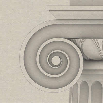
Points E and F mark the horizontal tangent or maxima of the second spiral and the first (outermost) spiral, respectively. The gap between them is exactly 4 parts or 32 units. GH is the profile for the vertical side surface on which part of the #ribbon and #braid lie flat, protruding exactly 6 units to coincide with the invisible virtual flat surface through EF.
The #cymaReversa is 2 parts or 16 units tall and 1.5 parts or 12 units wide. It starts 4 units to the right of F and stops 4 units short of the top fillet, which is one part or 8 units tall and 20 parts or 160 units from the #columnAxis.
Of the 4 parts or 32 units between G and H, the lower 3 parts or 24 units are part of the #voluteChannel groove and the top 1 part or 8 units is a fillet that follows the curve of the #volute and progressively gets narrower until it converges with the #eye of the volute.
We already made the 8 unit tall #fillet at the bottom of the #capital a part of the #shaft in https://pixelfed.social/p/Splines/791794072490907090. So, excluding that, the remainder of the capital is 14 parts or 112 units tall, for the bottom half of which we use the #revolve operation (like the #columnBase and #columnShaft), and for the top half we use the #extrude operation (like the #pedestal, #entablature, and #plinth).
Starting at the bottom, we have an #astragal that is 2 parts or 16 units tall and has the same profile as a #reed and #torus, falling in between the two in terms of size. The arc AD is shown in gray because it is an invisible #virtualSurface that envelops the decorations like #eggsAndDarts on the #ovolo. This is the measurement that is given in #Scarlata's #PracticalArchitecture, but it makes no mention of the #decorative and #tectonic surfaces. Arc BC with a radius of 4 parts or 32 units is the tectonic surface on which the Ovolo decorations rest. Such decorations have a variable or uneven surface which may not exceed 1 part or 8 units.
Points E and F mark the horizontal tangent or maxima of the second spiral and the first (outermost) spiral, respectively. The gap between them is exactly 4 parts or 32 units. GH is the profile for the vertical side surface on which part of the #ribbon and #braid lie flat, protruding exactly 6 units to coincide with the invisible virtual flat surface through EF.
The #cymaReversa is 2 parts or 16 units tall and 1.5 parts or 12 units wide. It starts 4 units to the right of F and stops 4 units short of the top fillet, which is one part or 8 units tall and 20 parts or 160 units from the #columnAxis.
Of the 4 parts or 32 units between G and H, the lower 3 parts or 24 units are part of the #voluteChannel groove and the top 1 part or 8 units is a fillet that follows the curve of the #volute and progressively gets narrower until it converges with the #eye of the volute.

Arcs and lines toil for #splines
2500 years ago, when they had neither computers nor #CAD tools, designers and architects relied on knowledge of algebra, geometry, and trigonometry for their daily work. It was a mere 350 years ago that Leibniz and Newton brought calculus as a new mathematical tool for design and engineering.
Before computers arrived, artists, designers, and architects toiled with manual drafting tools to engineer breathtaking masterpieces. "Toil" is not an exaggeration to describe that endeavor, even though I suspect some of them really enjoyed what they were doing.
#Scarlata compiled an entire book on #VignolaProportions with painstaking accuracy and high precision before there were calculators and spreadsheets, making it "easy" to convert from µ to physical units in both English and Metric systems, but the world has moved on, his work is forgotten, and nobody is thankful for his contributions.
If you have a CAD tool, you need not toil. Simply draw an arc of radius µ = 144 that is centered on the #columnAxis and passes through point B. Then draw a vertical line parallel to the column axis at x = µ * 5/6, or 120 units. Use this line to split the arc and trim away the left portion of the arc. Next, divide the length of the remaining portion of the arc into 8 equal portions using your CAD tool to mark points 1 through 8 as shown. If your CAD tool is able to divide the leftover arc this way, you can just ignore the angular lines radiating from the center. Otherwise, I will show you how to use them as a fallback.
Now look at point C, which seems like it is vertically above point B, but it is not. It is actually vertically above point 1.
Draw 7 more vertical lines starting with point 1, then point 2, and so on. Mark point C at 192 units vertically above on line 1, D at 192*2 on line 2, E at 192*3 on line 3, and so on until you reach point J.
Select these 8 points and use your CAD program to interpolate a free-form NURBS curve to fit these points.

Plan for #ColumnShaft of #IonicColumn
The #shaft of an #Ionic column is not perfectly cylindrical but gradually tapers off in the top 2/3 of the shaft. As such, the #primaryProfileCurve is not a straight line, nor is it composed of regular arcs. Instead, it is a complex amalgam of straight lines, circular arcs, and #NURBS curves, where the fancy acronym stands for an even fancier name — "Non-Uniform Rational B-Splines."
So, the promise [https://pixelfed.social/p/Splines/789956327130679640] was that we were going to get through this by drawing just straight lines and arcs. How are we going to draw NURBS? The answer is that we won't. The #CAD program will, as long as we give it sufficient information to carry out the task.
There are three NURBS curves in the profile shown in the plan. The longest and the most important one is between the points marked C through J. There is a smaller one between B and C, and an even smaller one between J and K.
While all three NURBS curves are mathematically similar, the information we must provide to the CAD program for the longest one is different from the other two short ones, and the operations the CAD program carries out to construct the longest one and the other two curves is also different.
This brings us to two new operations — #interpolate or "fit through points," and #blend shapes (existing curves or surfaces). When you choose a CAD program, make sure it supports NURBS, #interpolation, and #blending.
Starting at the bottom of the shaft, point A is 144 units from the #columnAxis, and so is point B, which is also 768 units higher than A. Starting with C through J, the points gradually move closer to the axis until J is exactly µ * 5/6, or 120 units from the axis. These points are equidistant vertically — all 192 units apart. However the horizontal distance is non-uniform.
In the next post we will mark the 8 points C through J using using one arc and 8 straight lines — I will keep my promise.

#IonicColumn #VignolaBase and #AtticBase #CAD Plans
Both #Vignola base and #Attic base have the same square footprint of 400 units x 400 units. The #plinth for both is 48 units (6 parts, or µ/3) tall, and the total height for both is 144 units (18 parts, or exactly µ). As such, they are easily interchangeable.
In the Vignola variant, we start at the plinth with a #fillet 2 units tall and a classic #scotia 18 units tall gouging out part of the fillet.
Then there is another fillet 2 units tall, followed by two #reeds, each 8 units tall, followed by another classic scotia as described above.
This is followed by yet another fillet 2 units tall and topped off with a #torus 40 units tall. A Torus is the same as a reed, except larger. When we reach the neck of the shaft, we will see another molding called #Astragal which has the same profile as reed and torus, but sits in the middle in size. Think of reed, astragal, and torus as small, medium, and large of the same profile.
The modern Attic variant is more elegant with fewer moldings. It also gives the impression of more heft for more stately columns. It starts at the plinth with a torus 36 units tall, followed by a fillet 4 units tall, followed by a modern scotia 24 units tall, followed by another fillet 4 units tall, and topped off with another torus 28 units tall.
As in the construction of #IonicEntablature [https://pixelfed.social/p/Splines/791013152244518907], split the construction of the #columnBase into two steps.
Just as we extruded #dentils separately, we extrude the plinth separately. First draw a square 400x400 in the top view. Then extrude the square 48 units in the front view.
For the rest of the base, we need a new 3D operation — #revolve around an axis. Instead of extruding the #primaryProfileCurve, we revolve it around the #columnAxis, and cap the #planarHoles on both ends before performing a #booleanUnion with the plinth. Finally check edges of the solid for #nakedEdges and #nonManifoldEdges.

If you've been longing for some 3D adventure, your wait is over. We have here some of the most basic 3D operations that you will use over and over.
First #join all #primaryProfileCurves into a single curve that has both straight lines and arcs. If you are unable to join them, look closely at the bottom #fillet of the #dado where it meets the top of the #reed of the #basement. There is a gap of 2 units between the fillet and the arc of the reed. Close the gap with a straight line and join the curves.
Switch from the front view to the right view, and #extrude the joined profile curves on both sides of the profile curve so that the full extrusion is a little over the total width of the pedestal. A good rule of thumb is to extrude at least 1/8th extra on both sides of the joined profile curve. This extrusion is shown in the attached image as the gray surface in perspective view.
Switch back to the front view and centered on the #columnAxis, draw a rectangle that is somewhat taller than the total pedestal height so that it extends past both the top and bottom of the pedestal extrusion from the previous step. The total width of this rectangle should be about 1.5 times the width of the pedestal. This is because we will create a cutting surface with this rectangle and rotate it 45° in the top view, and then rotate a copy of that another 90°, as shown by the flat red surfaces. The reason the width must be approximately 1.5 times (or larger) is because #Pythagoras told us that the hypotenuse of a unit square is 1.414 units. So 1.5 times should be enough.
Use the two cutting planes to cut, split, or trim the extruded surface (depending on the terminology of your CAD program). This is called #mitering. Discard the excess of the extruded surface from both ends. Also discard or hide the red mitering surfaces.
Switch to the top view and rotate the #mitered extrusion repeatedly at 90° about the column axis until you have all four sides, and join them all into an open surface.

This shows macro-level measurements for the #IonicPedestal.
The key to #effectiveModeling is to simplify a complex shape into elementary components. Sometimes, this involves mentally flattening and reducing 3D shapes to 2D shapes, extracting elementary curves from them, and then recreating the 3D shapes from the extracted 2D curves.
This is not always easy for organic shapes (which can still be approximated by Bézier curves). I extracted the #primaryCurves for the #IonicScroll surface in https://pixelfed.social/p/Splines/789956327130679640 after a lengthy trial-and-error process that involved #curveFitting images from #Vignola’s book, #RegolaArchitettura. I had to #reverseEngineer the details because the measurements have either been lost, or are locked away in some library. Web search yields no details on these measurements.
Fortunately, for geometrical shapes like pedestals, this is very easy. Because of its square footprint, mentally slicing it through the middle from top to bottom, it is easy to “see” the outline. Another way to think about #curveExtraction is to shine an imaginary bright light on an object from behind in a dark room to reveal its silhouette.
For the pedestal, even this silhouette or outline can be further reduced because the shape is symmetrical about the #columnAxis. With this realization, we only need to focus on one half of the outline, and methodically proceed from bottom to top, marking every kink and inflection point on the outline.
Fortunately, the other authoritative book, #Scarlata’s #PracticalArchitecture, I mentioned in my introductory post already documents #VignolaProportions in tabular form. So we can skip everything else and go directly to that.
Total height of #IonicPedestal is 864 units (108 parts, or 6*µ) of which the #PedestalBasement and #PedestalCap are each 72 units (9 parts, or µ/2) and the #Dado is 720 units (90 parts, or µ*5) tall.

>> Using µ = 288… pedestal height would be… 864 units.
The pedestal is the easiest to construct and requires only a rudimentary knowledge of geometry.
You only need to draw straight lines and arcs for the #profileCurves in 2D space (Front view), extrude the curves in 3D space, miter cut the ends at 45° (Top view), then rotate the mitered extrusion along the central #columnAxis at 90° intervals, making copies as you go.
Finally, you join and cap the extrusions.
Client Info
Server: https://mastodon.social
Version: 2025.07
Repository: https://github.com/cyevgeniy/lmst