Left side of this diagram shows the #profileCurves for the cap of #ModernIonicCapital from the front. The right side shows a perspective view of the cap surfaces obtained by revolving the profile curves about their respective axes and after some of those have been trimmed away
The measurements for the floor plan of the modern ionic capital are given in https://pixelfed.social/p/Splines/807782440025967685 with further links to relevant pages in #Scarlata's book at the bottom.
I won't bore you with the bottom portion of the modern #capital because it is very similar to that of the classic capital shown in https://pixelfed.social/p/Splines/792124787573855518. A significant difference is that the bottom #ovolo is shorter, with a total height of 32 units instead of 40
For the cap, we need two identical copies of a single profile curve that is 30 units wide and 48 units tall. The curves marked by A and B in the diagram are oriented in the same direction and are spaced 100 units from each other.
The bottom of profile curve A lines up with the neck of the #columnShaft at 120 units from the column axis. The revolution axis for this curve is located at 416 units from the column axis at the center of the largest circle in the floor plan.
We #revolve profile curve A full circle about its revolution axis. Then, we #rotate the resulting surface about the column axis to get 4 identical copies.
We revolve profile curve B full circle about the column axis. Then, we trim the resulting surface along with the 4 others at each intersection to get the side and corner surfaces for the cap of the capital.
We #join the trimmed surfaces, cap #planarHoles to convert them into a closed solid, and verify that the resulting solid is #airtight with no #nakedEdges and no #nonManifoldEdges.
The cap is in the correct final orientation. The volutes will be at 45° angles, but when we construct them, it will be easier to rotate the whole plan 45° so that the #volute #spiral is on the XZ plane.
#ColumnShaft

Plan for the #ModernIonicCapital
If the design in https://pixelfed.social/p/Splines/807569519962747338 looks daunting, let me assure you it is far simpler than the work that went into the reconstruction of just the #scroll for the #classicIonicCapital. Be sure to check out #MileStone4 at https://pixelfed.social/p/Splines/795361973789834465.
With the modern #IonicCapital, the designers went back to the basics of using just straight lines and circular arcs to define the geometry of the essential elements of the capital. No #braids, #keystones, or #modillions, and no #helix curves or #sinusoids.
We start the floorplan for the modern ionic capital with a circle of radius 5/6 of µ (120 when µ = 144) which marks the neck of the #columnShaft.
Tangent to this circle is a large circle of radius 296 units centered on the X axis exactly 416 units from the column axis. This is the circle that marks the curve of the #abacus, which is always tangential to the column shaft at the neck. This circle also marks the curved faces of the interior portion of the #volute wedge. Without the raised volute spirals, the interior wedge appears flush with the abacus as they follow the same circular arc.
Concentric to this large circle is another circle with a radius of 280 units to mark the extent of the raised volute spirals which are 16 units thick. Another concentric circle of radius 266 units marks the outer edge of the top of the capital.
The gap between the outermost large circle and the innermost concentric circle is 30 units, and that is reflected in another pair of circles centered on the column axis with radius of 250 units and 220 units to define the four corners.
The capital footprint fits in a square 396 units wide — or 24.75 parts horizontally from axis, per #Scarlata in https://babel.hathitrust.org/cgi/pt?id=mdp.39015031201190&view=1up&seq=45.
Use this with the sketch in https://babel.hathitrust.org/cgi/pt?id=mdp.39015031201190&view=1up&seq=142

Classic #IonicCapital #Tectonic Surfaces Plan
We already made the 8 unit tall #fillet at the bottom of the #capital a part of the #shaft in https://pixelfed.social/p/Splines/791794072490907090. So, excluding that, the remainder of the capital is 14 parts or 112 units tall, for the bottom half of which we use the #revolve operation (like the #columnBase and #columnShaft), and for the top half we use the #extrude operation (like the #pedestal, #entablature, and #plinth).
Starting at the bottom, we have an #astragal that is 2 parts or 16 units tall and has the same profile as a #reed and #torus, falling in between the two in terms of size. The arc AD is shown in gray because it is an invisible #virtualSurface that envelops the decorations like #eggsAndDarts on the #ovolo. This is the measurement that is given in #Scarlata's #PracticalArchitecture, but it makes no mention of the #decorative and #tectonic surfaces. Arc BC with a radius of 4 parts or 32 units is the tectonic surface on which the Ovolo decorations rest. Such decorations have a variable or uneven surface which may not exceed 1 part or 8 units.
Points E and F mark the horizontal tangent or maxima of the second spiral and the first (outermost) spiral, respectively. The gap between them is exactly 4 parts or 32 units. GH is the profile for the vertical side surface on which part of the #ribbon and #braid lie flat, protruding exactly 6 units to coincide with the invisible virtual flat surface through EF.
The #cymaReversa is 2 parts or 16 units tall and 1.5 parts or 12 units wide. It starts 4 units to the right of F and stops 4 units short of the top fillet, which is one part or 8 units tall and 20 parts or 160 units from the #columnAxis.
Of the 4 parts or 32 units between G and H, the lower 3 parts or 24 units are part of the #voluteChannel groove and the top 1 part or 8 units is a fillet that follows the curve of the #volute and progressively gets narrower until it converges with the #eye of the volute.

The bottom 1/3 of the #columnShaft for an #IonicColumn is a perfect cylinder. So the line below point B is a straight line.
In https://pixelfed.social/p/Splines/791723063470910081, we blended the bottom end of the 60° arc and the top end of the long interpolated curve between points J and K. Now blend the bottom end of the interpolated curve and the top end of the straight line between points B and C to obtain the 3rd and final #NURBS segment for the #primaryProfileCurve of the shaft.
Just like there's a #cavetto and #fillet near the #neck of the shaft, there is a fillet and cavetto near the foot of the shaft. However, there is a subtle difference between the two. The cavetto near the neck is tangential to the blended #NURBS curve that is not a straight line. The profile curve for the cavetto near the foot is tangential to a straight line.
There is a special name for a cavetto that is tangential to a straight line or flat surface, like the two cavetto moldings in the #dado of the #pedestal. It's called a #conge. Another alternate name for the cavetto molding is #cove, which is evocative of "cave" because of its concave profile curve.
Above the neck is a fillet 8 units tall and an #astragal 16 units tall that #Scarlata puts in braces in the column shaft section within his tables of #VignolaProportions, with a note saying they are not counted as part of the shaft but are accounted for as part of the #capital.
I decided to include the top fillet as part of the shaft and keep the astragal with the capital. It does not change the design or alter the proportions in any way, but the inclusion of the fillet makes it more practical for #3DPrinting and #CNCMilling of the neck. This concludes the profile curve for the shaft with a height of 291 parts or 2328 units + 8 for fillet.
The column shaft is tapered in the upper 2/3 due to #entasis whose purpose is to make optical corrections to the shape of the column which, without correction, appeared concave near the top.

Plan for #ColumnShaft of #IonicColumn
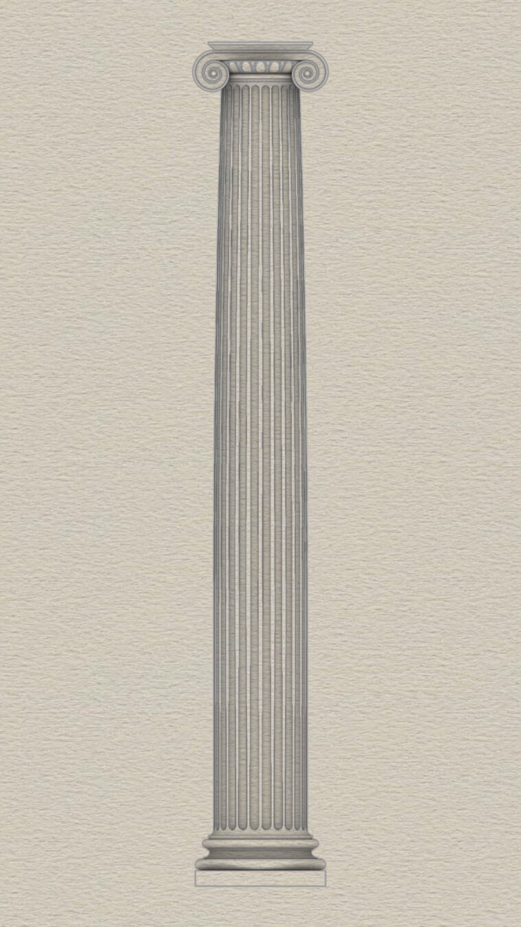
The #shaft of an #Ionic column is not perfectly cylindrical but gradually tapers off in the top 2/3 of the shaft. As such, the #primaryProfileCurve is not a straight line, nor is it composed of regular arcs. Instead, it is a complex amalgam of straight lines, circular arcs, and #NURBS curves, where the fancy acronym stands for an even fancier name — "Non-Uniform Rational B-Splines."
So, the promise [https://pixelfed.social/p/Splines/789956327130679640] was that we were going to get through this by drawing just straight lines and arcs. How are we going to draw NURBS? The answer is that we won't. The #CAD program will, as long as we give it sufficient information to carry out the task.
There are three NURBS curves in the profile shown in the plan. The longest and the most important one is between the points marked C through J. There is a smaller one between B and C, and an even smaller one between J and K.
While all three NURBS curves are mathematically similar, the information we must provide to the CAD program for the longest one is different from the other two short ones, and the operations the CAD program carries out to construct the longest one and the other two curves is also different.
This brings us to two new operations — #interpolate or "fit through points," and #blend shapes (existing curves or surfaces). When you choose a CAD program, make sure it supports NURBS, #interpolation, and #blending.
Starting at the bottom of the shaft, point A is 144 units from the #columnAxis, and so is point B, which is also 768 units higher than A. Starting with C through J, the points gradually move closer to the axis until J is exactly µ * 5/6, or 120 units from the axis. These points are equidistant vertically — all 192 units apart. However the horizontal distance is non-uniform.
In the next post we will mark the 8 points C through J using using one arc and 8 straight lines — I will keep my promise.

The #column is the most complex component — not least because of the beautiful #capital at the top. It also offers the most opportunities for creative expression, as long as designers differentiate in the #decorativeElements, not #tectonicElements.
There are 3 subcomponents of a column — the #columnBase, #columnShaft, and #columnCapital. In the #IonicOrder, there are variants for each of these components, not just in the tectonic portions, but also in the decorative portions, and it is equally acceptable to mix and match them.
Classic variant of the column #base bears #Vignola's signature in a new #molding called #scotia. There's a "modern" version that has a newer Scotia. I am trying hard to resist the urge to call it #NovaScotia.
The column #shaft is not perfectly cylindrical. It gradually tapers off in the upper 2/3, has a plain unadorned variant, and a #fluted variant.
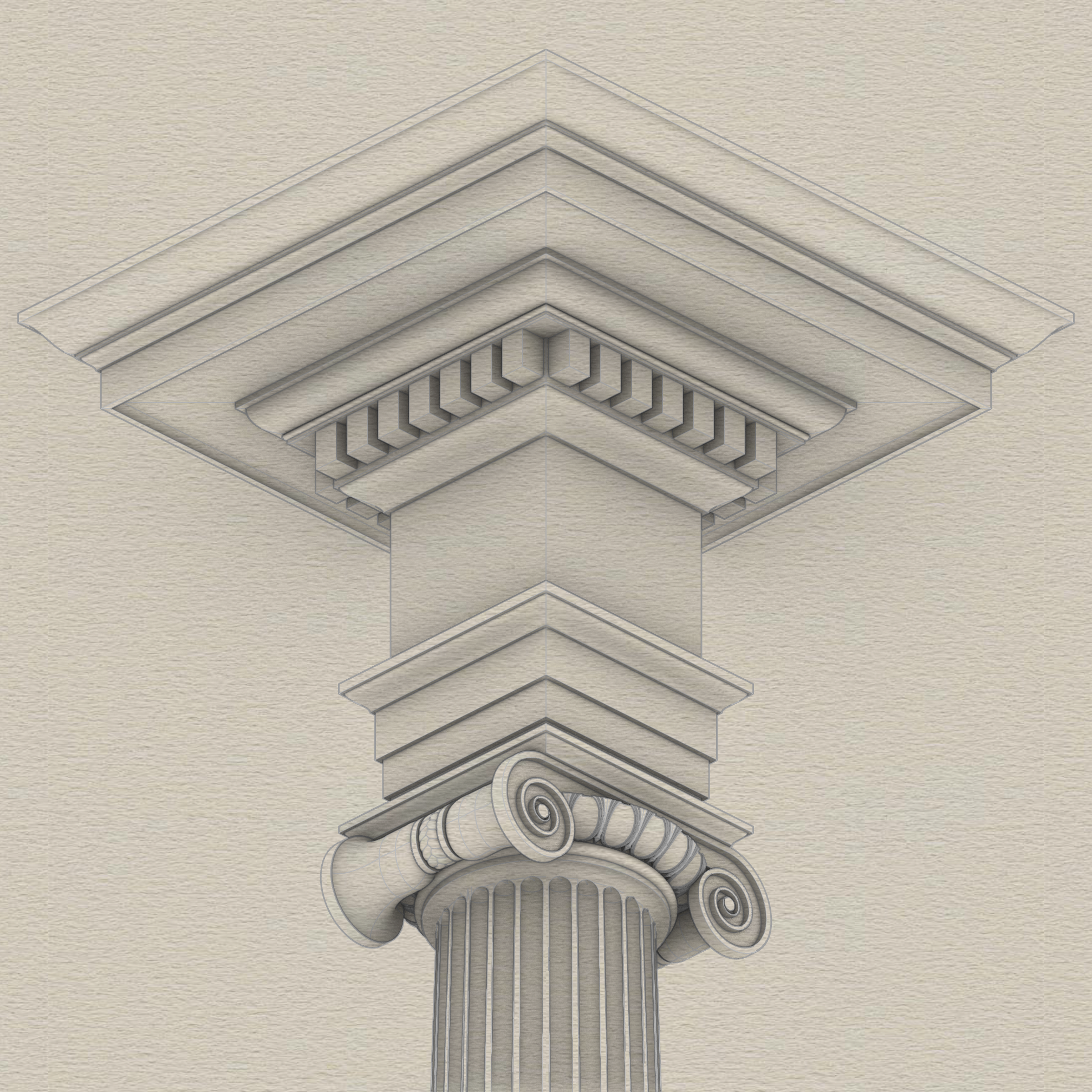
Classic variant of the column #capital has parallel flat #volute slabs only visible from the front and back, but not from the sides. There's also a modern variant that has curved volute faces on all four sides with pointed ends at all corners and optimized for use in a corner column, but not limited to that.
These variants can be freely intermixed in any combination of base, shaft, and capital. The sketch shows an Ionic column with a modern base, fluted shaft, and classic capital, but any other combination would be equally acceptable as long as all are internally consistent in a single #colonnade or #arcade.
Beyond these tectonic elements, there are decorative elements like the #eggsAndDarts motif in the #ovolo of the capital. The eggs can be convex or concave, the eggs and arrows can look different, or the Ovolo could have a completely different motif, or none at all.
The bell-shaped #scrolls between volute slabs are separated by a ribbon or belt with a 3-strand braid not seen in this sketch. If you design fashion accessories, experiment with other designs while maintaining proportions.
There are 3 subcomponents of a column — the #columnBase, #columnShaft, and #columnCapital. In the #IonicOrder, there are variants for each of these components, not just in the tectonic portions, but also in the decorative portions, and it is equally acceptable to mix and match them.
Classic variant of the column #base bears #Vignola's signature in a new #molding called #scotia. There's a "modern" version that has a newer Scotia. I am trying hard to resist the urge to call it #NovaScotia.
The column #shaft is not perfectly cylindrical. It gradually tapers off in the upper 2/3, has a plain unadorned variant, and a #fluted variant.
Classic variant of the column #capital has parallel flat #volute slabs only visible from the front and back, but not from the sides. There's also a modern variant that has curved volute faces on all four sides with pointed ends at all corners and optimized for use in a corner column, but not limited to that.
These variants can be freely intermixed in any combination of base, shaft, and capital. The sketch shows an Ionic column with a modern base, fluted shaft, and classic capital, but any other combination would be equally acceptable as long as all are internally consistent in a single #colonnade or #arcade.
Beyond these tectonic elements, there are decorative elements like the #eggsAndDarts motif in the #ovolo of the capital. The eggs can be convex or concave, the eggs and arrows can look different, or the Ovolo could have a completely different motif, or none at all.
The bell-shaped #scrolls between volute slabs are separated by a ribbon or belt with a 3-strand braid not seen in this sketch. If you design fashion accessories, experiment with other designs while maintaining proportions.
⬆️ @Carlbovis
Convince me that classical #architecture and #design were not influenced by #nature.
For context, compare the picture of #ChaffinchWings and tail in the previous post to the #volute and the #frieze in the sketch below which shows the classical #Entablature, #Capital, and neck of the #ColumnShaft in the #IonicOrder.
Client Info
Server: https://mastodon.social
Version: 2025.07
Repository: https://github.com/cyevgeniy/lmst