#IonicColumn #Flutes
In https://pixelfed.social/p/Splines/799864068250003272 I mentioned rounding off the radius of the bottom circle, but you don't have to. #CAD tools are perfectly happy working with 15.0728 or even higher precision as they are with 15.
After placing the two circles as described in that post, use the full #primaryProfileCurve of the shaft from https://pixelfed.social/p/Splines/791794072490907090 as a #sweepingRail and the two circles for the flutes as the #sweepingCurves, and #sweepOneRail for the body of a single flute. Close #planarHoles on both ends to get an #airtight solid.
Then draw a sphere at the center of the top circle using the same radius as the circle, and perform a #booleanUnion between the sphere and the flute body.
If you want a round bottom for the flute, repeat the sphere at the center of the larger circle using the same radius (15.0 or 15.0728) and perform another boolean union to get one flute.
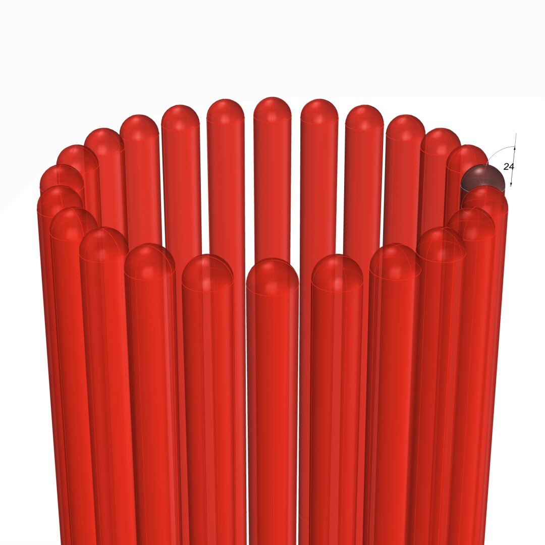
Switch to the top view and make 24 copies of the flute (including the original) centered at the column axis and #group the 24 flutes.
Finally, perform a #booleanDifference with the flutes group on a copy of the solid #unadornedShaft to get a fluted variant.
The result is a column shaft with flutes carved out. Save the flutes separately for future reuse.
This concludes the entire #IonicOrder, including all #decorativeElements.
Now we pause and reflect: The whole exercise seemed like one of #art and #sculpture. Where is the #architecture in all of this?
Without a ceiling or a roof, there is no building. Without additional columns or walls, there is no ceiling. So, while we have completed the Ionic Order itself, we only have the first #buildingBlock — a single column.
Next step is to repeat the columns to create a #colonnade, which together with supporting walls or additional colonnades can support a ceiling.
Just like with everything else in design, there are rules of proportion for #intercolumniation, or space between columns.
#booleanUnion
#Braids #3StrandBraids #MulticoloredBraids
To preserve the ability to print different strands in different colors when #3DPrinting, we must keep them separate. When #CNCMilling a block of wood or other material, we don't need to keep the strands separate.
To accommodate both kinds of output, I suggest that you keep the strands separate until the very end, and perform a #booleanUnion at the last possible stage after making a copy of the separate strands.
The topmost part of the diagram shows what the strands look like after a boolean union. Much of the internal structure is absorbed in the channel block, and overlapping parts of individual strands are eliminated.
The magenta curve from https://pixelfed.social/p/Splines/798252244743520392 is also shown here. Note that the location of the red cutting planes has changed slightly — Instead of 40 units from the origin, the first cutting plane is located at 39 because I ran into another limit that we must avoid.
Also, we need two blocks 120 units and 32 units long (not 24 units as was erroneously mentioned earlier). Turns out that cutting the strands at 32 units from the first cut puts us at 71 units from origin, and we run into another limit that destroys the #airtight properties of the cut solids. To get around that, we place the second cutting plane at 72 from origin to get a block 33 units long. The last cutting plane is at 159 units from origin, and when used with the first cutting plane it gives us a block 120 units long.
The lower portion of the diagram shows individual strands cut using the cutting planes as described above.
Depending on precision, you might or might not see a #nonmanifoldEdge on the second strand when cutting a length of 33 units. With precision set to 1/10 micron, which is ~100 times finer than current high-end #3DPrinters, I got a non-manifold edge.
Sometimes the fix is easy — Just #explode the solid, and rejoin the tiny surface fragments. Experiment with different precision settings.

We completed the #primaryProfileCurves for the classical flat #IonicVolute in https://pixelfed.social/p/Splines/792616677005177924.
To create a 3-dimensional slab with a recessed #channelGroove for the volute, you will need an outline of the volute without the inner #spiral arms.
To create the outline, make a copy of the spiral curves and work on the copy so that you don't destroy the originals. Drop a straight vertical line from the start point of outer Arc 1 of the spiral to the maxima or horizontal tangent of outer Arc 5. Trim away all other interior spiral lines and close the curve as shown in the left figure.
#Extrude the closed outline curve front to back by 1 part or 8 units in the side view. Extrude the #closedCurve of the inner and outer spirals by 2 parts or 16 units in the side view (but without the 6 unit extention on the top, which is only used when integrating the volute face with the #capital). Perform a #booleanUnion of both solids, and remember to check for #nakedEdges and #nonManifoldEdges.
The #volute design can be used outside of the #IonicColumn, such as in a #medallion. For a medallion, you have two options regarding the size of the enclosing circle.
You can either use the circle that Arc Zero lies on, or you can use the circle that Arc 1 lies on. Obviously, the latter is more compact. Just remember that the center for the larger circle is #groundZero or point 4 and the center for the smaller circle is point 1. In either case, inset the chosen circle with a concentric circle whose radius is 1 part or 8 units less.
The figure on the right shows the outlines of the enclosing circles based on the size of Arc 1 with center at Point 1.

#IonicColumn #VignolaBase and #AtticBase #CAD Plans
Both #Vignola base and #Attic base have the same square footprint of 400 units x 400 units. The #plinth for both is 48 units (6 parts, or µ/3) tall, and the total height for both is 144 units (18 parts, or exactly µ). As such, they are easily interchangeable.
In the Vignola variant, we start at the plinth with a #fillet 2 units tall and a classic #scotia 18 units tall gouging out part of the fillet.
Then there is another fillet 2 units tall, followed by two #reeds, each 8 units tall, followed by another classic scotia as described above.
This is followed by yet another fillet 2 units tall and topped off with a #torus 40 units tall. A Torus is the same as a reed, except larger. When we reach the neck of the shaft, we will see another molding called #Astragal which has the same profile as reed and torus, but sits in the middle in size. Think of reed, astragal, and torus as small, medium, and large of the same profile.
The modern Attic variant is more elegant with fewer moldings. It also gives the impression of more heft for more stately columns. It starts at the plinth with a torus 36 units tall, followed by a fillet 4 units tall, followed by a modern scotia 24 units tall, followed by another fillet 4 units tall, and topped off with another torus 28 units tall.
As in the construction of #IonicEntablature [https://pixelfed.social/p/Splines/791013152244518907], split the construction of the #columnBase into two steps.
Just as we extruded #dentils separately, we extrude the plinth separately. First draw a square 400x400 in the top view. Then extrude the square 48 units in the front view.
For the rest of the base, we need a new 3D operation — #revolve around an axis. Instead of extruding the #primaryProfileCurve, we revolve it around the #columnAxis, and cap the #planarHoles on both ends before performing a #booleanUnion with the plinth. Finally check edges of the solid for #nakedEdges and #nonManifoldEdges.

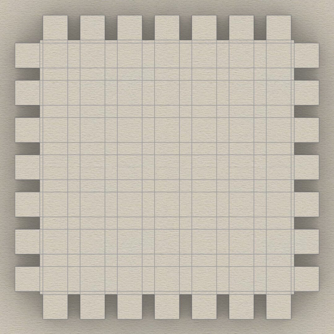
This sketch shows the arrangement of #dentils in the classic variation of the #IonicEntablature. It shows the full layout, but most of the top is obscured by the top portion of the #cornice. Only the outside square shapes are actually visible.
Each #dentil has a square "footprint" that is 4 parts by 4 parts (32*32 units) and is 6 parts (48 units) tall. The spacing between each dentil is 2 parts (16 units).
Dentils project 4 parts (or 32 units) from the face of the #fascia on which they rest.
Each face of the fascia has 7 dentils with the middle dentil laterally centered and directly in front of the column axis. The 2 side dentils are on side faces, and that is apparent in the darker shading in the sketch at https://pixelfed.social/i/web/post/790782316675150160. Take the time to reconcile this with the numbers listed in #Scarlata's #PracticalArchitecture.
The 3D reconstruction from the #primaryProfileCurves is very similar to that of the #IonicPedestal, with #extrusion, #mitering, #joining, and #capping planar holes as described in https://pixelfed.social/i/web/post/790645054230337543 — just set the dentils aside, for now.
Once you have capped the #planarHoles to get a solid, analyze the edges of the solid in the #CAD program for #nakedEdges and #nonManifoldEdges.
Then, extrude the dentils outline (in the top view) to a height of 48 units (in the front view).
Now perform a #booleanUnion of the two solid shapes to get the complete #entablature.
Finally, check the edges of the solid in the #CAD program AGAIN for #nakedEdges and #nonManifoldEdges.
With this, we have finished two of the three main components of the #IonicOrder. There's a modern version of the Ionic entablature with #modillions, which I will describe later.
Next, we move on to the biggest, most conspicuous part of the order — the #IonicColumn.
Client Info
Server: https://mastodon.social
Version: 2025.07
Repository: https://github.com/cyevgeniy/lmst