
OneROM RAM Mode Turns ROMs Into RAM
#OneROM #VIC20 #RetroComputing #Commodore #6502 #HardwareHacking #OpenSourceHardware #PIO #DMA #RP2350
https://theoasisbbs.com/onerom-ram-mode-turns-roms-into-ram/?fsp_sid=1534
#PIO


今更だけど
ラズパイPico、PIOなんてあったの???
そう言えば RP2040 のデータシート、読んだ事なかったかも… :blobdoggoglarethink:
やる事やったら読んでみよう!

🌘 利用 RP2040 驅動 TFEL 顯示器:逐步卸載 CPU 負載
➤ 解構 RP2040 PIO 驅動 TFEL 顯示器的技術細節
✤ https://www.zephray.me/post/rpi_pico_driving_el/
本文詳細介紹如何利用 Raspberry Pi RP2040 微控制器及其 PIO (可程式化 I/O) 功能,逐步實現驅動 640x480 像素的雙掃描單色 TFEL 顯示器,並有效將影像輸出任務從 CPU 核心卸載。作者首先說明瞭傳統透過 GPIO Bit-Bang 的方法會佔用大量 CPU 資源且影響時序精確度,隨後引入 PIO 的概念,並分階段展示如何利用 PIO 的自動推拉和側邊設定功能,建立兩個同步的狀態機來處理畫面資料的輸出,最終成功實現了流暢且無閃爍的畫面顯示。
+ 這篇文章對於如何善用 RP2040 的 PIO 進行低階硬體控制非常有啟發性。我之前一直煩惱著如何高效驅動高解析度顯示器,這提供了很好的思路。
+ 實作細節很紮實,尤其是關於兩個 PIO 狀態機
#嵌入式系統 #RP2040 #PIO #TFEL 顯示器 #嵌入式開發

Разбираемся с композитным видеосигналом NTSC, и стоит ли изучать его в 2025 году. Часть 2
В предыдущей статье я рассказал об основах композитного видеосигнала NTSC. Эта статья должна быть интереснее, так как она посвящена программной генерации такого видеосигнала. Тема интересна тем, что помимо самого видеосигнала вы ещё получаете множество практических навыков применения современных микроконтроллеров. Сигнал CVBS можно получить, используя и FPGA-решения, но стоимость их выше, чем у микроконтроллеров, таких как Raspberry Pi Pico или ESP32. Я использовал платы разработчика на базе микроконтроллера RP2040. На рынке существует несколько таких плат. Классика — это Raspberry Pi Pico, но есть несколько китайских аналогов, например, YD-2040. Отдельно хочется выделить RP2040 Zero от Waveshare — очень компактное решение, правда у него отсутствует порт для отладки, но можно обойтись и без порта. Важный момент — СVBS-сигнал является аналоговый, поэтому стабильность напряжение на выходе играет важную роль и для приемлемого качества сигнала китайские клоны Raspberry Pi Pico могут не подойти, так как они страдают нестабильным напряжением на выходах. Мой совет — используйте или оригинальный Raspberry Pi Pico или RP2040 Zero от Waveshare. Желающих продолжить чтение приглашаю под кат.
#ntsc #raspberrypi #raspberry_pi_pico #cvbs #композитный_видеосигнал #r2r_dac #DMA #PIO #прерывания #ruvds_статьи

Разбираемся с композитным видеосигналом NTSC, и стоит ли изучать его в 2025 году. Часть 2
В предыдущей статье я рассказал об основах композитного видеосигнала NTSC. Эта статья должна быть интереснее, так как она посвящена программной генерации такого видеосигнала. Тема интересна тем, что помимо самого видеосигнала вы ещё получаете множество практических навыков применения современных микроконтроллеров. Сигнал CVBS можно получить, используя и FPGA-решения, но стоимость их выше, чем у микроконтроллеров, таких как Raspberry Pi Pico или ESP32. Я использовал платы разработчика на базе микроконтроллера RP2040. На рынке существует несколько таких плат. Классика — это Raspberry Pi Pico, но есть несколько китайских аналогов, например, YD-2040. Отдельно хочется выделить RP2040 Zero от Waveshare — очень компактное решение, правда у него отсутствует порт для отладки, но можно обойтись и без порта. Важный момент — СVBS-сигнал является аналоговый, поэтому стабильность напряжение на выходе играет важную роль и для приемлемого качества сигнала китайские клоны Raspberry Pi Pico могут не подойти, так как они страдают нестабильным напряжением на выходах. Мой совет — используйте или оригинальный Raspberry Pi Pico или RP2040 Zero от Waveshare. Желающих продолжить чтение приглашаю под кат.
https://habr.com/ru/companies/ruvds/articles/961086/
#ntsc #raspberrypi #raspberry_pi_pico #cvbs #композитный_видеосигнал #r2r_dac #DMA #PIO #прерывания #ruvds_статьи
🌘 Raspberry Pi RP2040 或 RP2350 軟體模擬實現 100 Mbit/s 乙太網路
➤ 微控制器效能極限的突破:用軟體模擬實現高速乙太網路
✤ https://www.elektormagazine.com/news/rp2350-bit-bangs-100-mbit-ethernet
開發者 Steve Markgraf 運用 Raspberry Pi Pico 上的 RP2040 (或更新的 RP2350) 微控制器,僅透過軟體和可程式化 I/O (PIO) 成功實現了 100 Mbit/s 的高速乙太網路傳輸。此專案繼先前軟體模擬 USB 之後,展現了 PIO 的強大潛力,能夠處理 MLT-3 編碼、4B5B 線路編碼及擾碼等複雜任務,並能達到每秒約 11 MB 的 UDP 串流傳輸量,可應用於低成本的高速資料擷取與串流情境。
+ 太令人驚訝了!竟然能用 RP2040 跑出 100M 的乙太網路,這對小型專案來說開啟了許多可能性。
+ 這真是個了不起的成
#嵌入式程式設計 #Raspberry Pi #RP2040 #RP2350 #乙太網路 #PIO

Arduino and SP0256A-AL2 – Part 3
Following on from using an Arduino as a variable clock in Arduino and SP0256A-AL2 – Part 2, I have some ideas for a few options, but this post looks in detail at using a Raspberry Pi Pico as the clock source.
Spoilers: it kind of works, but isn’t quite the answer I need yet…
- Part 1 – Basic introduction and getting started
- Part 2 – Arduino programmable clock
- Part 3 – Using a Raspberry Pi Pico as a programmable clock
- Part 4 – Using a HC4046 PLL as the clock
- Part 5 – Using an I2C SI5351 programmable clock
- Part 6 – Adding MIDI
https://makertube.net/w/bxBYCqHrZvQLwLuwYa5Z9r
Warning! I strongly recommend using old or second hand equipment for your experiments. I am not responsible for any damage to expensive instruments!
If you are new to microcontrollers, see the Getting Started pages.
Using a RPi Pico
The RP2040 can be overclocked quite a bit, so generating a variable square wave up in the few MHz range should presumably be relatively straight forward. Using the built-in PIO state machines for a square wave is fairly simple and it can be done from Circuitpython or Micropython too.
This is a complete square wave generator for GP2 that steps down from 4MHz to 2MHz in steps of 100kHz. It can optionally overclock the RPi to 250 MHz too if required.
import time
import microcontroller
import board
import rp2pio
import adafruit_pioasm

square = adafruit_pioasm.assemble ("""
.program square
    set pins, 1
    set pins, 0
""")

RP2040Freq = 125_000_000
#RP2040Freq = 250_000_000

print ("RP2040 Frequency = ", microcontroller.cpu.frequency)
microcontroller.cpu.frequency = RP2040Freq
time.sleep(1)
print ("New RP2040 Frequency = ", microcontroller.cpu.frequency)

while True:
    for freq in range (4000000, 2000000, -100000):
        print("\nReqd frequency = ", freq*2)
        print("Sq frequency = ", freq)

        sm = rp2pio.StateMachine(
            square,
            frequency=freq*2,
            first_set_pin=board.GP2,
        )
        print("Actual freq = {:d}".format(sm.frequency))
        print("Actual sq freq = {:d}".format(int(sm.frequency/2)))

        time.sleep(5)
        sm.deinit()
The PIO program itself has two instruction steps, so takes two cycles to complete, so the running frequency has to be twice the desired frequency of the square wave. It automatically keeps looping, so no additional instructions are required there.
The state machine will run at the system speed with a 16.8 fixed point fractional clock divider. Full details can be found in section 3.5.5 “Clock Dividers” in the RP2040 datasheet.
For certain values there might be some jitter:
If the system clock is faster though, the amount of jitter will be less I suspect, so it is advantageous to overclock the Pico for more accurate frequencies.
The problem with this approach is that whilst I get a nice accurate clock source with quite a good resolution across its range, every time the state machine is recreated to change the frequency, there is a “blip” in the audio from the SP0256A-AL2 whilst its clock temporarily disappears!
An alternative approach is to use a fixed state machine frequency but include a counter in the PIO program to allow for a configurable number of steps per scan of the PIO without having to stop and restart the clock.
The problem with this is that I am limited to a unit of the instruction time for the PIO state machine which gives a fixed overhead, in terms of the instructions required for a minimal loop, and a flexible overhead, in terms of the counter I can pass in.
The upshot of this is that I’m tied to a certain resolution of frequency change.
I have the following PIO code:
.program blink
.side_set 1
.wrap_target
    pull noblock
    mov x, osr
    mov y, x
    set pins, 1
lp1:
    jmp y-- lp1
    nop
    nop
    mov y, x
    set pins, 0
lp2:
    jmp y-- lp2
.wrap
The “pull” will update the output shift register (OSR) either with any new value written to the state machine or the last value of the X register. This value gets copied to Y to use as a counter. This happens twice, once for when the pin is set at 1 and once for when the pin is set at 0.
There are two nops whilst the pin is set at 1 to balance for the original pull and mov instructions at the end of the pin set to 0 cycle.
As the Y counter value is used twice, the flexible overhead of the timing is essentially proportional to count * 2. It counts for the pin being HIGH and then for the pin being LOW.
The fixed overhead is the cost of the original pull, two moves, the pin sets, and a single jmp per pin state – so by using the two nops to ensure the HIGH and LOW times are the same, that is 10 instruction cycles.
I was hoping to use the “side” instruction to eliminate the two set instructions, but so far I’ve not managed to get that to work. I still don’t understand PIO…
So for now the timing of the PIO routine is = 10 + 2 * count and the unit is the time for a single instruction, which is 1 / frequency of the PIO execution, up to a maximum frequency of the Pico’s system clock frequency.
Using an overclocked Pico at 250MHz, the frequency range would start at the following:
- Execution freq = Pico Sys Clock / (10 + 2 * count)
- So when count = 0; execution freq = 250MHZ / 10 = 25 MHz
That is far too fast for the SP0256A-AL5. In fact, I’ve found that anything over around 5MHz causes the chip problems.
For this reason, I’m using a minimum count of 20:
- Max execution freq = 250MHz / (10 + 2 * 20) = 5 MHz
Plotting execution frequency per “count” value (starting from 20) gives the following:
We can see the limits of the resolution at the top-end, and in fact, the first few equivalent frequencies in that range are as follows:
CountEquivalent Frequency205,000,000214,807,692224,629,629234,464,285244,310,344That is giving me something like a 150-200kHz jump each time, which isn’t great, but is probably the best I can do. I would be larger if I wasn’t overclocking the Pico. It does get smaller as the count increases, but it is only really worth going down to a count value of around 120, which is around 1MHz for the resulting clock. Anything lower than that and the SP0256A-AL2 isn’t particularly useful.
Here is the full Circuitpython code which attaches a pot to GP26 to control the frequency in the range of around 900kHz up to 5MHz. Note the scaling of the pot value (0 to 65535) by 600 prior to its use to add to the count.
import array
import time
import board
import rp2pio
import microcontroller
import adafruit_pioasm

from analogio import AnalogIn
algin = AnalogIn(board.GP26) # ADC0

blink = adafruit_pioasm.assemble(
    """
.program blink
.side_set 1
.wrap_target
    pull noblock
    mov x, osr
    mov y, x
    set pins, 1
lp1:
    jmp y-- lp1
    nop
    nop
    mov y, x
    set pins, 0
lp2:
    jmp y-- lp2
.wrap

"""
)

RP2040Freq = 250_000_000

microcontroller.cpu.frequency = RP2040Freq
time.sleep(1)

oldalgval = 0

sm = rp2pio.StateMachine(
            blink,
            frequency=RP2040Freq,
            first_set_pin=board.GP2
        )
sm.write(bytes(16))

while True:
    algval = algin.value
    if (algval != oldalgval):
        oldalgval = algval
        count = 20 + int(algval / 600)
        freq = int (RP2040Freq / (10 + count*2))
        data = array.array("I", [count])
        sm.write(data)

    time.sleep(0.2)
One problem will be the 3V3 operating levels of the Pico. The SP0256A-AL2 datasheet states the following:
So whilst a “high logic” value for the oscillator has a minimum level of 2.5V, it also states that a minimum of 3.9V is required if driven from an external source.
If required, something like a 74HCT14, powered by 5V, can be used to level shift the 3V3 output of the Pico to a 5V signal for use with the SP0256A-AL2.
But in practice, I was finding the Pico worked fine as is. It is important to ensure both the Pico, Arduino and SP0256A-AL2 all have their grounds connected.
A this point I’m just using the Pico as a programmable clock, but if I was to go this route, then it would make sense to have the Pico drive the SP0256A-AL2 too and forgo the Arduino.
Closing Thoughts
So I have two choices if I want to use a Raspberry Pi Pico:
- Go for smooth changes of frequency, but with less resolution, especially at the higher frequencies.
- Go for more accurate resolution across the range but accept there will be blips when the clock changes which will be heard in the audio.
Neither is a perfect solution, but it shows the principles are valid. Also, using two microcontrollers is a bit over the top, so if I was to move to using a Pico, I’d probably want to find a way to drive the SP0256A from the Pico directly too and skip using an Arduino.
One benefit of that would be that I can time the frequency changes to coincide with silence in the speaking should I wish to, avoiding the possibility of major audio blips.
But I also have a few other options to try, which I’ll come back to in a future post.
Kevin


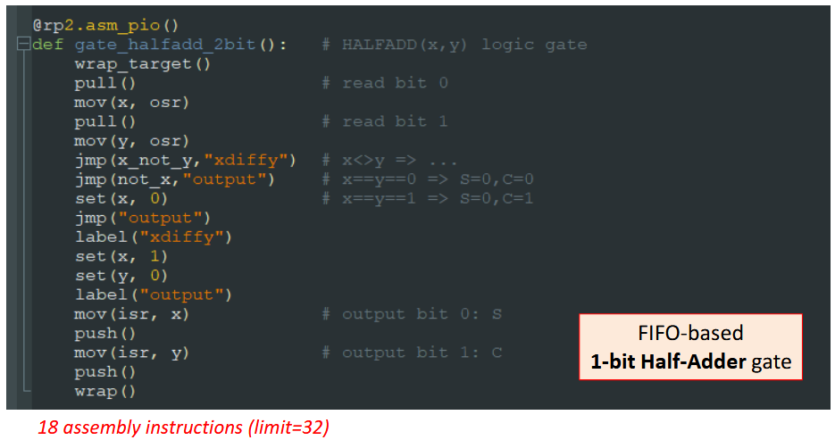
"Yes, A.I. still sucks at coding in some cases — For now…"
Article in AI Advances, 17-Jun-2025
---
Summary: Testing the limits of LLMs in code gerenation for Raspberry Pi Pico PIO assembly, as well as an example of how we design modern CPUs microcodes. If you work in these fields, your job is still pretty much secured against AI for many years...
>> https://medium.com/ai-advances/yes-a-i-still-sucks-at-coding-in-some-cases-for-now-828a0fc17ada
#AI #PIO #assembly #programming #Micropython #raspberrypi


Aviation weather for Captain Renán Elías Olivera International airport in Pisco area (Peru) is “SPSO 131900Z 30006KT 270V330 3000 BR OVC017 19/16 Q1013 RMK BIRD HAZARD RWY 22/04 PP000” : See what it means on https://www.bigorre.org/aero/meteo/spso/en #pisco #peru #captainrenaneliasoliverainternationalairport #spso #pio #metar #aviation #aviationweather #avgeek #airport vl
Riddle:
Executing a WAIT instruction with 24 delay cycles should take 25 cycles in total
Except?
nop 24 waits 14 cycles to and including out pins
nop 26 waits 15 cycles to and including out pins
nop 25 waits 15 cycles to and including out pins
nop 14 waits 9 cycles to and including out pins
so 10 nops is 5 cycles? WTF!?
What am I missing or overlooking here?
#raspberrypio #pico #pio #rp2040 #rp2350
(4/4)

Erasing meaning is the whole point of making it an acronym if you're a #GOP #PIO
Like saying #BLM instead of #BlackLivesMatter
Like talking about a #COLA instead of a #CostOfLiving Increase
They only say " #CriticalRaceTheory " bc they know those are the three scariest words their base can hear (after "taxes")
Создаём эмулятор легендарной игры «Ну, Погоди» на базе Raspberry Pi Pico
Многие из тех, кому сейчас за 30, и рождённых в СССР или на постсоветском пространстве, помнят электронную игру «Ну, погоди!». Во времена, когда не было ни интернета, ни ноутбуков, ни мобильных телефонов, а из общедоступных электронных развлечений были только аттракционы в парках культуры и видеосалоны, обладание бытовым компьютером, электронными наручными часами Montana или электронной игрой «Ну, погоди!» было мечтой многих детей. Были ещё и другие электронные игры, но именно «Ну, погоди!» считается классикой. Игре посвящено много ностальгических статей и видео. На различных торговых площадках можно купить её в различном состоянии от убитого до «с хранения» и даже новодел. Лет 10 назад и я купил её в идеальном состоянии, поигрался, вспомнил детство и положил в ящик. Но несколько месяцев назад с разочарованием увидел, что «потекла» нижняя часть экрана. Можно было или отремонтировать, или купить другой экземпляр игры, но я сначала попробовал узнать, как её отремонтировать, а потом решил воссоздать игру на современных компонентах. Я не был одинок в своём желании воссоздать игру, этой теме посвящено также немало статей, но в них обычно создавали симуляторы, а не эмуляторы игры. Симулятор у меня ассоциируется с фразой: «Я художник, я так вижу», эмулятор — это более точное воспроизведение устройства. Формат статьи не позволяет выразить все те ощущения, которые я испытал при путешествии от зарождения идеи до реально работающей игры, практически ничем не отличающейся от оригинала. Много из того, что я узнал в этом путешествии, не поместилось в статью или поместилось в очень сжатом виде. Эмулятор максимально приближен к оригиналу, если не считать экран (он не сегментный, как в оригинале) и корпус (я пока реализовал на беспаечной макетной плате). Если вам интересно, как за несколько вечеров воссоздать у себя эмулятор «Ну, погоди!» на современном микроконтроллере или просто поностальгировать, добро пожаловать под кат.
https://habr.com/ru/companies/ruvds/articles/889414/
#ruvds_статьи #raspberry_pi_pico #pio #dma #эмулятор #ну_погоди #fritzing

Capping my work for @adafruit this week with the first working demo for pi5 with the "active3" RGB matrix adapter.
This adapter lets you push out about 3x as many pixels per unit of time, which mean you can either improve your refresh rate or drive more pixels with the same refresh rate.
Mapping these pixels is more complicated than with a single matrix connector, so the open pull request punts and just makes you write the pixel map in Python. This is evaluated just once at your program startup, keeping the pixel mapping part of the code fast when you update the screen contents.
I hope that a future improvement will supply some standard mappers for 2- and 3-connection display setups; at a minimum, I'd like it to work when each strand is a single panel or string of linear panels, and they're in horizontal or vertical stripes.
Anyone know if the Circuitpython Neopixel implementation uses PIO on the RP2040? The existence of neopixel_write in the HAL for CP implies it does...
But if so, what if you have an application that also wants to use PIO? How are conflicts managed?
Another bit of my @adafruit work is ready to escape out into the world. Introducing https://github.com/adafruit/Adafruit_Blinka_Raspberry_Pi5_rp1pio
rp1pio is intended to be a compatible subset of CircuitPython's rp2pio module, except instead of being for the rp2040 and rp2350, it's for the Raspberry Pi 5, which has an "RP1" I/O coprocessor chip.
The library is capable of running two examples: driving neopixels (though there's also a dedicated Python package for this, which is recommended instead), and decoding signals from a "quadrature encoder".
This doesn't replicate all the functionality you know and love from the rp2040 but it's a start, and we welcome community involvement to add more features.
I'll be showing the rotary knob functionality off on Show & Tell. Our live broadcast on youtube starts in about 15 minutes: http://adafru.it/live

The library for driving HUB75 style matrices on Pi5 computers is released: https://github.com/adafruit/Adafruit_Blinka_Raspberry_Pi5_Piomatter https://pypi.org/project/Adafruit-Blinka-Raspberry-Pi5-Piomatter/
Exclusive of imports, here's how you can display a 64x64 png on an pair of attached 64x32 matrices:
geometry = adafruit_raspberry_pi5_piomatter.Geometry(width=64, height=64, n_addr_lines=4, rotation=adafruit_raspberry_pi5_piomatter.Orientation.Normal)
framebuffer = np.asarray(Image.open("blinka64x64.png")
matrix = adafruit_raspberry_pi5_piomatter.AdafruitMatrixBonnetRGB888Packed(framebuffer, geometry)
matrix.show()

input("Hit enter to exit")
You can also play an image sequence (code in the github repo, find your own images); here, it's an excerpt from Big Bug Bunny reduced to 32x64 resolution. In person it's nice and flicker free, the phone camera just makes it look bad.

I'm playing Pioneer Masters Drafts, live now at https://twitch.tv/mad_moses Come hang out! #mtg #arena #pio #draft #limited #MagicTheGathering
Dinrova exactsies on 1 life https://www.twitch.tv/mad_moses/clip/TentativeOriginalMochaFloof-7pOnHdvRkezlRRP-
#mtg #mtgarena #MagicTheGathering #pio #draft
progress: chained rgb matrix displays on pi5 using pio. these are using the common "serpentine" arrangement where the 2nd display is rotated 180 degrees.
tired now, didn't yet push the code.

Client Info
Server: https://mastodon.social
Version: 2025.07
Repository: https://github.com/cyevgeniy/lmst