
Follow-up question: Your digital attenuator has some RF coming out of its MOSI pin. What do you do? #electronics #rfengineering #hamradio
#RFEngineering
you have a 1117 feeding a few digital chips and a digitally selectable attenuator on a medium sized mixed signal board. How many 2k7@100MHz ferrite beads in series is excessive?

Understanding LoRa Modulation: How Chirps Enable Long Range Wireless Communication
1,523 words, 8 minutes read time.
Long Range (LoRa) modulation is one of the most innovative digital radio techniques available today, widely used in IoT networks and by hobbyists exploring the potential of long-distance low-power communication. At its core is Chirp Spread Spectrum (CSS) — a method that spreads information across a frequency sweep, rather than encoding it solely on amplitude or phase. This allows signals to travel far, penetrate obstacles, and resist noise better than many traditional modulation schemes.
LoRa emerged in the 2010s as engineers sought low-power solutions for sensors, meters, and devices that needed to communicate over kilometers without draining batteries. While it’s most commonly associated with the Internet of Things, the principles behind LoRa have direct relevance to amateur radio enthusiasts, particularly those interested in long-distance digital modes. Understanding the physics of chirps, spreading factors, and symbol encoding is not just theory; it forms a foundation for grasping modern RF communications.
This document explains LoRa’s modulation in detail, highlighting why CSS is effective, how chirps encode data, and why receivers can detect signals far below the noise floor. By mastering these concepts, aspiring operators build a deep understanding of frequency manipulation, signal correlation, and processing gain — skills applicable well beyond LoRa itself.
What is Chirp Spread Spectrum (CSS)?
Chirp Spread Spectrum is a type of wideband modulation where the frequency of a signal linearly increases or decreases over time. These sweeping frequencies, called chirps, encode data based on their timing and phase relative to other chirps. This technique originates from radar and sonar, where chirps help detect weak echoes over noisy backgrounds. LoRa adapts this concept for digital data transmission, using chirps to represent symbols rather than simple binary states.
Unlike traditional amplitude or frequency shift keying, which toggles between discrete values, CSS spreads information over the entire bandwidth. This not only improves robustness against interference but also provides processing gain, allowing the receiver to extract weak signals buried in noise. The result is a system capable of communicating over distances and under conditions where conventional narrowband radios would fail.
LoRa’s implementation of CSS further optimizes the technique by introducing cyclic shifts of chirps. Each unique shift represents a distinct symbol. By adjusting the starting point of a chirp within its sweep, LoRa encodes multiple bits per symbol. This design creates a high-efficiency, M-ary modulation system that balances range, sensitivity, and data rate.
Finally, the spreading factor (SF) determines how many symbols are available per chirp. Lower SFs mean shorter chirps, higher data rates, and shorter range, while higher SFs produce longer chirps, lower data rates, but vastly improved sensitivity. This flexibility allows LoRa to scale performance based on specific application needs, from dense urban deployments to remote rural sensors.
How LoRa Encodes Data with Chirps
Each LoRa symbol represents multiple bits, encoded by cyclically shifting a chirp within the channel bandwidth. For example, a spreading factor of SF = 7 allows for 128 possible shifts per symbol, while SF = 12 offers 4096 options. Each shift is precisely timed and frequency-controlled, effectively turning a frequency sweep into a rich constellation of data points.
The receiver decodes these chirps using correlation detection. By comparing received signals with reference chirps, the system identifies the correct cyclic shift and extracts the underlying symbol. This approach allows the receiver to recognize signals far below the noise floor, a capability uncommon in most conventional digital modes.
The combination of cyclic shifts, spreading factors, and correlation detection allows LoRa to operate in environments that would challenge standard FM or digital radio systems. Devices can coexist on the same frequency channel with different SFs due to the orthogonality of the chirps. This means that a gateway can simultaneously detect multiple transmissions, improving network capacity and reliability.
Finally, the choice of bandwidth directly influences symbol rate and sensitivity. Narrower bandwidth increases the time per chirp, enhancing sensitivity and range but reducing throughput. Wider bandwidth allows faster communication at the cost of reduced link margin. LoRa’s careful balance of these parameters makes it highly adaptable for a wide variety of low-power, long-range applications.
Why LoRa Works Below the Noise Floor
One of LoRa’s most remarkable traits is its ability to decode signals significantly below the noise floor. Traditional radios fail when the signal drops just a few decibels below noise. LoRa achieves this due to the processing gain inherent in CSS and the correlation properties of chirps.
When a chirp is received, the system performs a correlation with a reference chirp, effectively summing energy across the entire symbol period. This accumulation allows the receiver to detect weak patterns that would otherwise be lost. Because random noise rarely mimics the predictable linear frequency sweep of a chirp, most interference is rejected naturally.
This property is why LoRa devices can communicate over kilometers while consuming only a few tens of milliwatts of power. A signal that would be undetectable with narrowband FM can be recovered reliably using a CSS receiver, enabling ultra-long-range, low-power networks.
Finally, this capability is invaluable to amateur radio operators exploring low-power, long-distance communication. By studying LoRa, operators learn how spread-spectrum techniques, correlation detection, and careful frequency planning can dramatically extend range without increasing power or bandwidth.
Spreading Factors and Network Design
The spreading factor (SF) in LoRa defines the number of possible chirp offsets and directly impacts performance. A lower SF enables faster data rates and shorter chirps, ideal for local communication or high-throughput applications. A higher SF produces longer chirps and more possible offsets, dramatically improving sensitivity and long-range performance.
Bandwidth, symbol duration, and spreading factor together determine time-on-air, affecting latency, throughput, and energy consumption. Network designers must balance these parameters to meet specific requirements, whether for a dense urban network or a remote sensing deployment.
Additionally, the orthogonality of chirps with different SFs allows multiple devices to transmit simultaneously on the same frequency. This property increases network capacity and reduces interference, a practical consideration for IoT networks, but also a valuable insight for amateur radio enthusiasts exploring multi-user digital modes.
Understanding these relationships is key for anyone interested in RF design or digital communication. By experimenting with different SFs and bandwidths, learners gain intuition about trade-offs in real-world wireless networks.
Practical Applications for Amateur Radio Enthusiasts
While LoRa is not a standard Amateur Radio mode, studying its modulation provides invaluable insights into RF engineering, digital signal processing, and wireless network design. Knowledge of CSS principles applies broadly, from HF digital modes to satellite communications and experimental high-frequency systems.
For the aspiring Amateur Radio operator, experimenting with LoRa modules or building custom receivers can teach critical skills: correlating signals, understanding link budgets, and designing for long-range communication in noisy environments. These lessons are directly transferable to more traditional ham radio projects.
Moreover, LoRa’s low-power, high-range performance inspires innovative approaches to emergency communication, remote monitoring, and experimental digital networks. Amateur operators who understand these concepts are well-positioned to contribute to novel applications, from sensor arrays to hybrid radio networks.
Finally, mastering LoRa principles strengthens the operator’s intuition about spectrum, modulation, and signal detection. It’s a practical, hands-on way to deepen RF literacy while staying on the cutting edge of low-power wireless technology.
Future Developments in Long-Range Wireless Communication
Chirp Spread Spectrum and LoRa modulation continue to influence research in low-power, resilient communication. Advanced networks, hybrid IoT-amateur setups, and urban sensor deployments all benefit from the core principles pioneered by LoRa.
Future enhancements may include adaptive spreading factors, multi-channel correlation, and improved interference mitigation, further extending range and reliability. As spectrum becomes more crowded, these techniques will be increasingly valuable for both commercial and hobbyist radio users.
For Amateur Radio operators, understanding LoRa’s underlying physics equips them for the next generation of digital radio experimentation. From long-distance sensors to robust low-power networks, the skills developed studying LoRa modulation have lasting relevance across the radio spectrum.
In summary, LoRa modulation demonstrates how clever manipulation of frequency, timing, and correlation allows information to travel far, efficiently, and reliably. By grasping chirp-based communication, aspiring operators gain expertise that strengthens both theoretical understanding and practical radio skills.
Call to Action
If this story caught your attention, don’t just scroll past. Join the community—men sharing skills, stories, and experiences. Subscribe for more posts like this, drop a comment about your projects or lessons learned, or reach out and tell me what you’re building or experimenting with. Let’s grow together.
D. Bryan King
Sources
- LoRa Alliance – LoRa & LoRaWAN Technical Book (PDF)
- LocalMesh – LoRa Technology Explained
- Raveon Technologies – LoRa Protocol Overview
- nolilab.com – Simple Guide to LoRa & LoRaWAN
- HamRadio.my – LoRa and CSS Modulation Explained
- All About Circuits – Demystifying LoRa Networks
- DN.org – Chirp Spread Spectrum Fundamentals
- Wikipedia – LoRa (Overview & PHY Layer)
- Medium – What Is LoRa: The Fundamentals
- The Things Network – Spreading Factors Explanation
- Gyulab – LoRa/CSS Overview, Demodulation & Decoding
- Wikipedia – Chirp Spread Spectrum (CSS)
- MOKOSmart – Technology Behind LoRa Frequency
- ADS/ArXiv – A Tutorial on Chirp Spread Spectrum Modulation
- arXiv – Design of LoRa Communication Systems Research
Disclaimer:
The views and opinions expressed in this post are solely those of the author. The information provided is based on personal research, experience, and understanding of the subject matter at the time of writing. Readers should consult relevant experts or authorities for specific guidance related to their unique situations.
#advancedModulation #AmateurRadio #amateurRadioProjects #bandwidthOptimization #chirpSpreadSpectrum #chirpWaveform #correlationDetection #css #CSSDesign #CSSTutorial #cyclicChirps #dataEncoding #digitalModulation #digitalRadioModes #digitalRFTechniques #digitalSignalTheory #frequencyHopping #frequencyModulation #frequencyShift #frequencySweep #hamRadio #highGainRF #highSensitivityRadio #interferenceRejection #IoTCommunication #IoTConnectivity #IoTDevices #IoTLinkMargin #IoTNetworks #IoTSensorNetwork #longDistanceData #longDistanceRadio #longRangeCommunication #longRangeIoT #LoRaApplications #LoRaGateway #LoRaModulation #LoRaNetwork #LoRaPHYLayer #LoRaReceiver #LoRaTechnologyGuide #LoRaWAN #lowNoiseDetection #lowPowerIoT #lowPowerRF #lowPowerSensors #lowPowerWireless #lowSNRCommunication #MAryModulation #processingGain #radioEngineeringPrinciples #radioFrequencySweep #radioHobbyist #radioHobbyistGuide #radioModulation #radioPropagation #radioProtocol #RFCommunicationGuide #RFCommunicationSystems #RFCommunicationTutorial #RFDesign #RFEngineering #RFExperimentation #RFExperimentationGuide #RFInnovation #RFLearning #RFPrinciples #RFSignalProcessing #RFSpectrumManagement #RFSpectrumTutorial #RFTutorial #RFWaveform #signalCorrelation #signalDetectionBelowNoise #signalRobustness #signalToNoiseRatio #spreadingFactor #subGHzBands #symbolEncoding #timeOnAir #ultraLongRange #widebandModulation #wirelessExperiment #wirelessLinkBudget #wirelessNetworkDesign #wirelessPerformance #wirelessSensors #wirelessSignal #wirelessSignalAnalysis #wirelessTechnology

Anybody have a good field strength meter schematic that they've actually built and used successfully? I'd like to build one sometime and trying to look one up online I get dozens of them of varying complexity.
#amateurradio #hamradio #radioengineering #RFEngineering #electronics #electronicengineering #RF
Admitted: Now I have enough RF power meters! 😂
But occasionally you strike luck and have to make a quick decision, which is why my Vintage 432A now has new friends 🙂
The probe for the Rohde@Schwarz NRVS covers to 6GHz and I scored an inline probe as well, which has a ceiling at 3 GHz. Neat!
The other two reaches 18GHz.
So who do you like more? 🙂🙂
BTW. Does anyone know how to enable display light on the NRVS? Can’t find a manual 🤷🏼♂️🤨
#rfengineer #rfengineering #electronics #testandmeasurement #hamr #hamradio
I needed an accurate attenuator for a work experiment I wanted to do at home (recovering from a dental surgery — I’m fine 🙂) and a friend had this beauty taking up space 🤷🏼♂️🙂 (I have good friends).
Clearly hand built (sorry for the shaky video), made to sit in a test rack, remote controlled by the vintage Z80x CPU board. It’s quite flat in its frequency response (I had troubles with the VNA calibration, so you’re seeing cable and connector loss) and I made a couple spot checks at 3 and 6GHz, 1.5 and 2.5dB loss respectively.
Attenuation accuracy is within +/- 1dB.
This is quality vintage stuff, dated about 2003 from the onboard chips. Don’t you just love the Teledyne RF relays? 🥰
Oh, and it works way below the stated 2GHz, I tested it down to 10MHz and it was just fine 👍🏼
#rfengineer #rfengineering #frequencyfriday #hamr #hamradio #testandmeasurement

📡 What is Microwave Engineering?
👉 Click here: https://engineersheaven.org/forum/topic/46
to visit our website and read the full article.
#MicrowaveEngineering #RadarTech #WirelessInnovation #TelecommunicationEngineering #SignalProcessing #RFengineering #AntennaDesign #FutureTech #STEMeducation #EngineersHeaven #EngineeringExplained
Don’t you just love it when vintage RF electronics springs back to life? 😃
My old fox hunt receiver, original design by #OZ1FSM, has survived a couple of relocations, but the batteries had leaked and it looked like a complete loss, unfortunately.
A couple hours of careful cleaning did the trick however, and now it’s back, alive and well with new battery holders and a couple of Lithium’s 😃
#hamradio #foxhunt #RFengineer #RFengineering #testandmeasurement
Spiral antennas are funny devices. They are known for their extremely wide bandwidth, the ones shown here, are specified to operate from 2-18GHz.
They’re not meant as transmitting antennas, these critters are receive-only, used by (largely non-civilian) pilots who have those needs ☺️
Their low frequency boundary is determined by its physical size, in this case, the circumference of the small plate where you can see the fine spiral traces.
Once you cross below that boundary, the structure basically collapses electrically, seen here as a steep SWR ‘wall’ to the left side of the sweep.
At this point it’s not an antenna anymore, but something else (whatever that is 🤷🏼♂️😂)
#rfengineering #rfengineer #testandmeasurement #hamradio #hamr #antennaengineering #emso
Testing a new 1:9 Unun I plan to use for a permanent non-resonant multiband vertical 🙂
#hamradio #testandmeasurement #measurementmonday #rfengineer #rfengineering #hamr #electronics #hamradiooperator
In November 2023, I experimented with directional finding using a ‘rat race’ 4 port coupler. The coupler outputs deliver the sum and difference of the received signals from the two antennas and at the difference (‘DELTA’) output, a reasonably sharp signal ‘null’ is present exactly between the antennas.
In principal this should also be doable by comparing the RSSI (signal strength) between two completely similar receiver chains.
Using two AD8317, wideband demodulating logarithmic amplifiers and two antennas, the DC voltage on the output can be displayed on the oscilloscope (yellow and blue trace), and more importantly, the difference (‘DELTA’) between them (red trace).
Moving an RF source in front of the antennas, it’s clear that the DELTA signal drops when the source is right between them, and rises again towards the edges.
RF filtering will be needed to limit the AD8317 10GHz bandwidth 🙂
#hamradio #rohdeschwarz #testandmeasurement #rfengineering #rfengineer #emso
2/2)
I decided to test it with a 0dBm RF source through an isolator and it clearly reacts to the small amount of applied power, moving from 2480 Ohm down to 2438 Ohm.
Any suggestions for more experiments? 🙂
#rfengineer #rfengineering #electronics #testandmeasurement #sensorsunday
1/2)
A fellow #hamradio operator and electronics enthusiast brought me a vintage X-Band power sensor, thanks OZ1ETE 🙂
It has a super sensitive NTC Thermistor, a tiny spherical bead, encapsulated inside a small glass tube. It’s by far the most sensitive Thermistor I’ve ever seen, just holding your hand in front of the waveguide flange, not actually covering it, will make it change slightly.
#rfengineer #rfengineering #electronics #testandmeasurement #sensorsunday
💡 Need more personalized help? Is your challenge more complex or unique, involving different specifications or circuit types?
🎯 We’ve got you covered!
🚀Don’t wait—contact @innowave for a quote on your RF circuit or radio design problems: https://buff.ly/3NPPCcn
🚀Contact @innowave for a quote on RF Circuit design and Measurement Training and Consultancy. https://buff.ly/3CcvzlY
#RFDesign #RadioFrequency #Electronics #PowerAmplifier #LNA #KeysightADS #RFEngineering #CircuitDesign
Believe it or not, approaching 40y as a #hamradio operator, I just got my first BIRD wattmeter 😃
Its in really nice shape, S/N 104908, I wonder how old it is 🤔
The hunt for ‘slugs’ 🐌 has started 🙂 It came with 50W 2-30, 25W 100-250 and 250W 400-1000. Would be nice with 100W for the shortwave bands and something which covers 6m 👌🏼

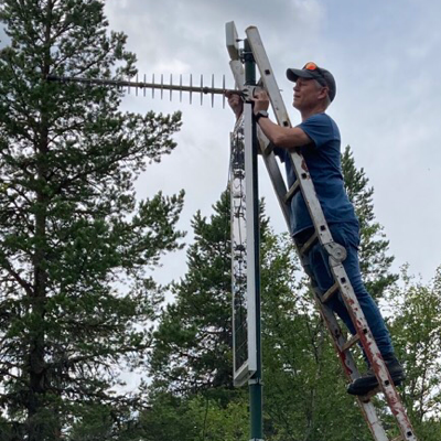
Always wanted a portable directional to spot emitters at higher frequencies - decided to try this one.
My test ceiling is 4GHz, but at least that far, it seems OK ✅🙂 I doubt it’ll go all the way to 10GHz as advertised because of the (FR4?) PCB Material.
It always amuses me, how violently antennas like this collapse at the lower frequencies - suddenly the size no longer accommodates the input wavelength and they simply stop being an antenna 🤷🏼♂️😂
For some reason, these logperiodic (LPDA) antennas always come with a SMA connector at the tip - that’s completely wrong: you need to solder a semirigid coax all the way down the centerline and feed it from there. The PCB was even prepared for it - go figure 🤷🏼♂️🤔
Anyway, now fixed, tested, and ready to go signal hunting 😎
#rfengineering #rfengineer #hamr #hamradio #testandmeasurement #antennaengineering #electronics #summervibes

🚀 New Video Alert! 🚀 Learn how to install HFSS on any Linux distro using Bottles. Perfect for antenna design and RF enthusiasts! 📡
Watch now: https://youtu.be/ydEOdOd2ZP8
#Linux #HFSS #Bottles #FlatSeal #AntennaDesign #RFEngineering #Antenna #RF #TechTutorial #PhDLife #LinuxInstallation #TechGuide @usebottles #flatpak #flathub @FlatpakApps @flathub @kubuntu #kubuntu #linuxMint #Telecommunications
I’ve been looking for an antenna for a permanent #meshtastic node in my attic and I found this one, along with 5m RF200 low-loss cable.
I know that this setup will most likely render me ‘excommunicado’ in the #meshtasticcommunity: “thou shalt always install thy node right below the antenna!”, but here’s the thing: I want to experiment with different hardware, I want to do some interference measurements at night (ever heard about the ‘Mammotion’ lawnmower which illegally jams 868MHz?) , AND I have a powerful 2m/70cm transmitter close to it, and I don’t want EMI issues on a sensitive 5V line.
Besides, the antenna has 3dBi gain and I measured the cable loss to 1.4dB at 868MHz, so given its better location, the numbers still come out positive 🙂
See that dip near 145MHz btw.? Need to do a test to see how much signal it’ll pick up from my VHF rig - don’t want to damage my LoRa module 👌🏼🙂
#lorawan #electronicsengineering #rfengineering #rfengineer #hamradio hamr #testandmeasurement
It’s #measurementmonday and I’m investigating a mystery coupler, a fellow ham asked me to test.
It seems to be the happiest around 1.8-1.9GHz 🤷🏼♂️🙂
The coupled ports are -20dB down.
What’s even more interesting, is the detector diode add-on it came with: you carefully insert the diode, a 1N21E replica, directly into the center pin of the N-connector 😳 Then carefully mount the outer capacitor shell with the BNC connector and you’re good to go.
Since the diode now sits in its reversed position, the output will be negative and it works just fine 👍🏼🙂
#testandmeasurement #hamr #hamradio #rfengineer #electronics #siglent #rfengineering


Client Info
Server: https://mastodon.social
Version: 2025.07
Repository: https://github.com/cyevgeniy/lmst