Mini 8×8 LED Matrix
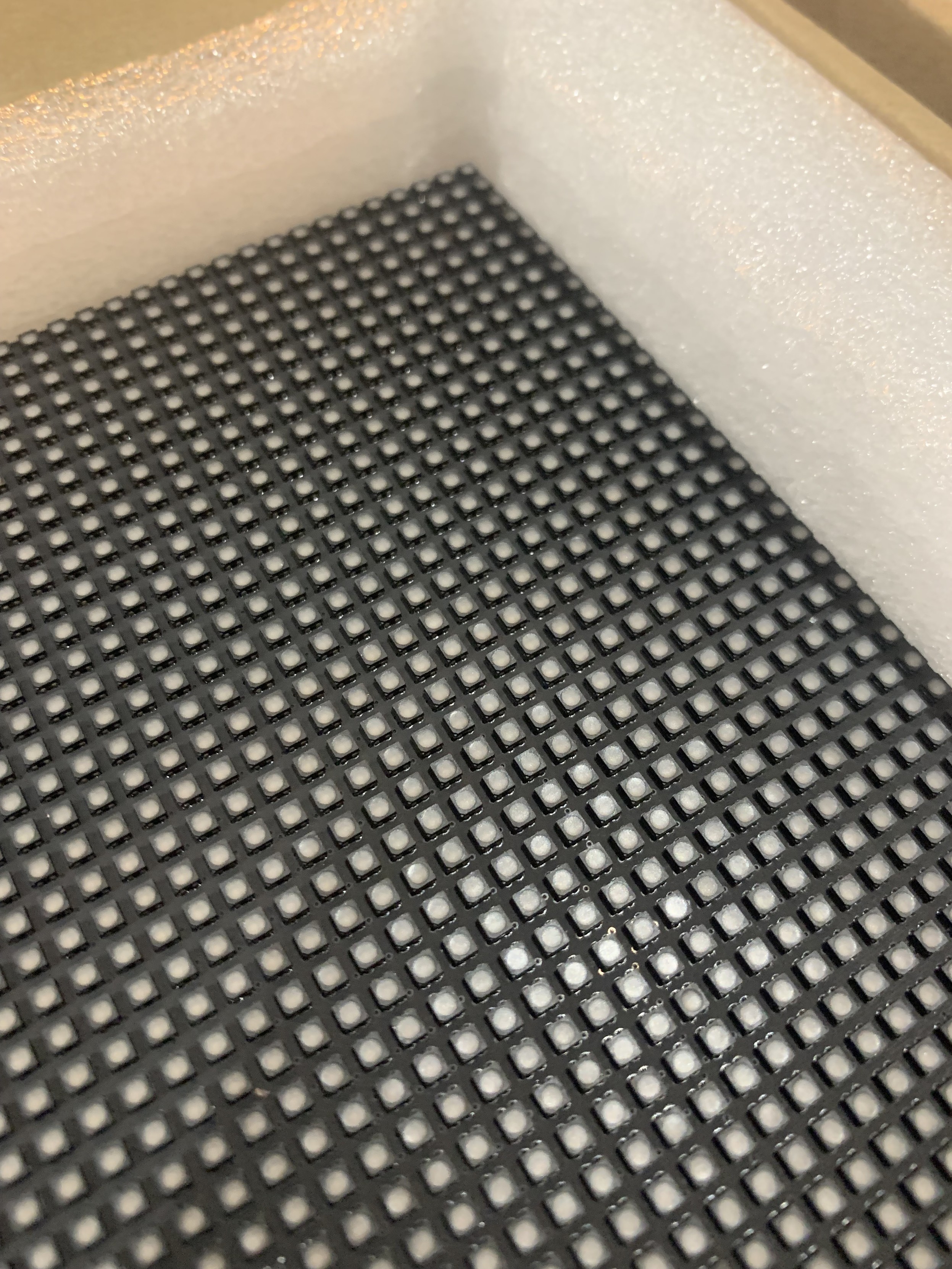
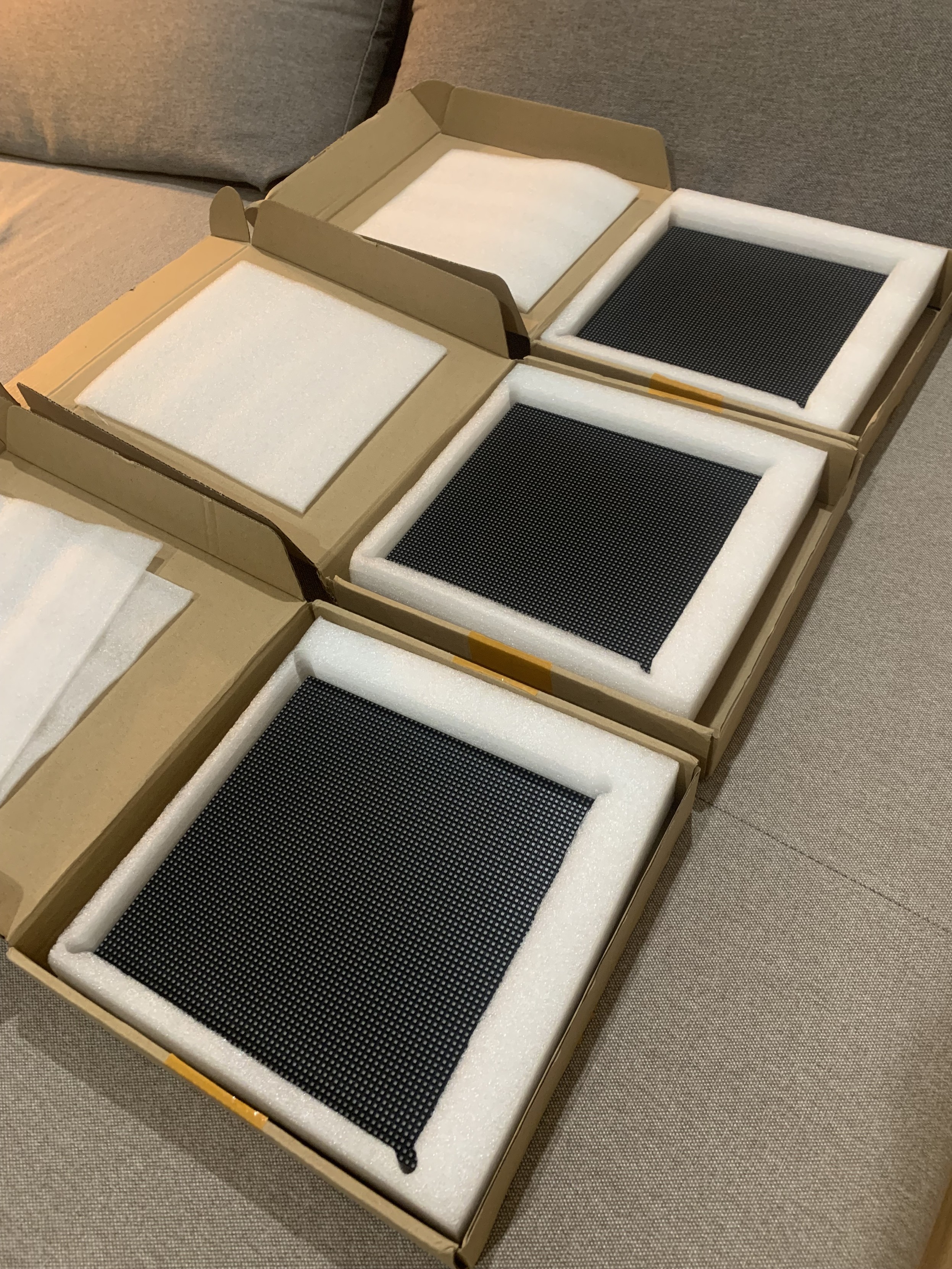
I have a few neat 20x20mm square 8×8 LED matrix modules that I want to drive.
Quite some time ago I tried to hook them up with a HT16K33 based 16×8 I2C LED matrix driver, but it was all on stripboard and not only was it quite messy, actually it really didn’t work very reliably either, so this is another attempt. Eventually this resulted in a small driver PCB.
The LED Matrix Module
The fundamental point of an LED matrix module is the matrix bit. The LEDs are arranged in a grid of some sort and consequently it isn’t possible to light up all LEDs at the same time. They have to be “scanned” and if they are scanned quickly enough then persistence of vision kicks in and it appears as if all LEDs are lit at the same time.
There are a whole range of 8×8 LED matrix modules to choose from, and often it isn’t obvious what the type or pinout for them is. At least it isn’t when they’ve been kicking around in your parts drawer for some time.
Options are:
- Size of module. I’m using a square mini module which is 20x20mm (often described as 19x19mm). A larger 8×8 version is the 32x32mm module. There are also asymmetrical arrangements too, for example 5×7 LEDs.
- Type of LED. I’m using single colour LED modules, but they are often available in different colours. There are also dual-colour versions (usually red and green, which also gives an orange option when both are lit) and even RGB versions. The RGB can be “programmable” LEDs or simply direct connections to each LED colour – so with RGB, that is 4 pins per LED…
- Common Anode or Common Cathode. This refers to which leg of a row/column or LEDs is common to that entire row/column.
- Number of pins and pinout. Different matrices are mapped onto pins differently. I’ve seen some with 14 pins and some with 16, both in DIP format.
- Arrangement of the “grid”. There are two main variants here – a grid with the same number of LEDS per common connection, or a “Charlieplexed” arrangement which is a clever way of driving more LEDs from less IO pins. I have a square grid of 8 rows and 8 columns of LEDs.
Here is a schematic with LED arrangement and pinouts for a common 8×8 LED module found very cheaply online.
The left shows a common cathode, and the right a common anode. I’m pretty sure I have common anode LEDs from an old note I found lying around, so I’m going to start with that.
I’ve used the following simple circuit to verify which pin is which. The resistor is there to limit the current passing through each LED.
In the final circuit, I’d be looking at maybe using a 1K resistor so limiting the LED current to around 3-3.5mA (assuming 5V supply and forward voltage of 1.7-2.2V for a typical red LED). For a maximum of 8 LEDs per common connection, that would still only be less than 50mA so I don’t think current would be an issue in any of the approaches I’ll be looking at. But I also have to take into account that if there are 8 scan cycles for a complete display, then each LED will only be on for 1/8th of the time of the scan, so will appear 1/8th as bright anyway.
I do seem to have a module that follows the pinout as shown above (right). In the following diagram, the pins are numbered with pins 1 to 8 along the bottom (left to right) and pins 9 to 16 across the top (right to left).
In this orientation, the ROWs and COLUMNs as described above are mapped as shown below.
Just to bring all this together, the pin functions of my matrix are as follows (row = anode; column = cathode):
PinPinR5116C8R7215C7C2314R2C3413C1R8512R4C5611C6R6710C4R389R1
LED Matrix Driving
The fundamental principle for a common anode configuration is that if a positive voltage is patched onto a ROW and GND is connected to a COLumn then that LED at that position will light up. However of course, different ROWs and COLs will have different states so some kind of “scanning” will be required.
A microcontroller can do this without any additional support if it has 16 IO pins. For example, the following algorithm could be used to scan each ROW in turn, setting the appropriate COL values:
Initialise ROW and COL pins as OUTPUT
Set all ROWS and COLS to LOW
FOR EACH ROW:
  FOR EACH COL:
    Set HIGH or LOW according to required output pattern for that ROW.
  Momentarily set ROW HIGH then return it LOW
Every COL/ROW LED will light up when the combination ROW=HIGH, COL=LOW is reached. If the ROWs are scanned quickly enough, then persistence of vision means that the LED matrix appears to be fully illuminated.
As I say, given suitable current limiting LEDs (one per ROW) and enough IO pins a microcontroller could do this directly, but it uses a lot of GPIO and is likely to reach the current limits of the microcontroller pretty quickly if lots of LEDs are illuminated at once.
The answer is to utilise an additional chip as an LED matrix driver, both freeing up the microcontroller’s GPIO and providing the option for a higher current draw.
LED Matrix Drivers
There are a number of options. Some are general IO expanders, some are dedicated to supporting LED matrices, some include higher current sinks or sources as required.
A key benefit of these types of devices is that in some the scanning is performed by the device itself, so the MCU only has to send it the data for the complete display and then let it just get on with things.
MAX2719 Segment Display Driver
This is a “Serially Interfaced, 8-Digit LED Display Driver” (more here). From the MAXIM datasheet:
“The MAX7219/MAX7221 are compact, serial input/output common-cathode display drivers that interface microprocessors (µPs) to 7-segment numeric LED displays of up to 8 digits, bar-graph displays, or 64 individual LEDs.”
They interface to a MCU using SPI and have additional features to directly support 7 or 8-segment displays. As they support up to 8 digits with up to 8 segments, they could also perfectly support my 8×8 LED matrix.
Key parameters:
- 24 pin DIP.
- MCU Interface: Serial IO (chainable).
- Power: 4.0V – 5.5V.
- DIG sink current: 500mA; SEG source current: 100mA. Max current supply (all segments on): 330mA.
These are often paired up with a 32mm 8×8 LED display on a cheap PCB kit. For my purposes though, there is an issue – these are designed to be used with common cathode displays.
I suspect this is due to the current ratings for the digit/segment pins. The datasheet expands:
“Eight-Digit Drive Lines that sink current from the display common cathode. The MAX7219 pulls the digit outputs to V+ when turned off.”
“Seven Segment Drives and Decimal Point Drive that source current to the display. On the MAX7219, when a segment driver is turned off it is pulled to GND.”
If the LEDs are in a matrix, in principle it ought to be possible to have an arrangement that could work with a common anode display if the current limits can be balanced.
The common cathode (DIG) will assume a worst case of all 8 LEDs illuminated, meaning a maximum sink of up to 500mA or up to around 60mA per LED. The individual anode (SEG) supports up to 100mA current source per LED. These are both pretty high, especially as I’m not anticipating more than a total of around 50mA for 8 LEDs.
But can a common cathode scanning chip be used with a common anode display? As it stands it will be assuming that it can set a single cathode line LOW and drive all 8 anode lines according to the required pattern. But as the LEDs are displayed in a matrix, looking back at the circuit diagrams, I think it just means that the cathodes are the columns and the anodes are the rows. So instead of scanning rows, it will be scanning columns, so I think it would be fine.
So to summarise, for my LED matrix, the ROWs will be the anode, so connected to SEG and the COLs will be the cathode so connected to DIG.
There is one other key advantage to using the MAX7219. It supports a single “current setting” resistor (Rset in the datasheet). A single resistor between the ISET pin (18) and VCC. Looking at the table in the datasheet I think using a ~60-80K resistor would keep he current down to <10mA for the LEDs, although I must admit I’m not quite following how the values are calculated.
IS31FL3731 LED Driver
The actual IS31FL3731 driver chip is a QFN-28 or SSOP-28 surface mount device, so I won’t be using these directly, but they are available in a breakout board from Adafruit (more here and here). From the datasheet:
“The IS31FL3731 is a compact LED driver for 144 single LEDs. The device can be programmed via an I2C compatible interface. The IS31FL3731 offers two blocks each driving 72 LEDs with 1/9 cycle rate. The required lines to drive all 144 LEDs are reduced to 18 by using the cross-plexing feature optimizing space on the PCB. Additionally each of the 144 LEDs can be dimmed individually with 8-bit allowing 256 steps of linear dimming.”
I believe by “cross-plexing” they are talking about “Charlie Plexing”. The breakouts have the following key parameters:
- SMD but available as a breakout.
- MCU Interface: I2C with 4 address options.
- Power: 2.7V – 5.5V.
- Pinout compatible with Adafruit 16×9 Charlieplexed LED modules.
These are available relatively cheaply (~£6 each) but they aren’t geared up for use with a common LED matrix like mine, so they won’t be considered further either. But I do have some of the modules and the corresponding LED boards, and I can confirm they are very neat and possibly the highest density LED matrix I have.
HT16K33 LED Controller
This is the driver chip Adafruit use on their own 20x20mm 8×8 LED matrix “backpacks” (more here). From the datasheet:
“The HT16K33 is a memory mapping and multi-function LED controller driver. The max. Display segment numbers in the device is 128 patterns (16 segments and 8 commons) with a 13*3 (MAX.) matrix key scan circuit. The software configuration features of the HT16K33 makes it suitable for multiple LED applications including LED modules and display subsystems. The HT16K33 is compatible with most microcontrollers and communicates via a two-line bidirectional I2C-bus.”
Key operational parameters:
- SMD but available as a breakout.
- MCU Interface: I2C with 8 address options (although only 4 are available on some of the backpacks themselves).
- Power: 4.5V – 5.5V (although the Adafruit backpacks look like they can be powered from 3V3 too).
- Available in 8×8 (20 pin), 8×12 (24 pin) and 8×16 (28 pin) variants, although Adafruit modules are only available in 8×16 format.
- 16x ROW = anode (active HIGH to display); 8x COL = cathode (active LOW to display)
- COL sink current: 200mA; ROW source current: <40mA
These are the modules I’d originally used with my first attempt (undocumented) at driving these LED matrix displays. If I was to use them again, then it would be a case of including the footprint on a PCB for a pair of LED matrices and then providing a connector for I2C and power.
Note: I can’t just use the Adafruit LED matrix breakouts directly as I want to cascade them up to each other and these breakouts have exposed PCBs top and bottom that stops the LED matrix from being positioned right next to each other.
MCP23017 IO Expander
This is a generic 16-way GPIO I2C expander providing access to an additional 16 GPIO pins over I2C (more here) – a “16-Bit I/O Expander with Serial Interface” according to the datasheet:
“The MCP23X17 consists of multiple 8-bit configuration registers for input, output and polarity selection. The system master can enable the I/Os as either inputs or outputs by writing the I/O configuration bits (IODIRA/B). The data for each input or output is kept in the corresponding input or output register. The polarity of the Input Port register can be inverted with the Polarity Inversion register. All registers can be read by the system master.”
Key parameters:
- 28 pin DIP.
- MCU Interface: I2C (23017) or SPI (23S17).
- Power: 1.8V to 5.5V.
- Max current sink/source for IO pins: 25mA; Max through VSS/VDD: 150mA/125mA.
These devices have two 8-bit GPIO ports, so it would seem a simple matter of hooking up one port to the rows and one to the columns and then it would work fine as a matrix driver. There are a couple of issues though:
- Each common connector IO pin to be scanned should allow for up to the maximum of 8 LEDs to be illuminated. If there is a 25mA limit per IO pin, that isn’t much per LED. It could be done, e.g. by using a 2K resistor with my red LEDs, but they might not be very bright. But they still might be bright enough depending on what is required.
- There is no built-in scanning, the microcontroller will have to constantly send the new IO values over I2C for each row or column scan. That will add up pretty quickly to become a limiting factor I suspect, especially as that has to be maintained at a suitable refresh rate.
Given the current limits and lack of automated scanning, whilst these could work, they offer very little advantage, and some disadvantage, compared to the other options.
74HC595 Shift Register
Whilst it is possible to drive LEDs directly from a microcontroller (assuming they can support the current), it is more usual to use a shift register to save IO pins.
“The SNx4HC595 devices contain an 8-bit, serial-in, parallel-out shift register that feeds an 8-bit D-type storage register.”
This means that 8-bits provided over a serial link get turned into 8 IO pin outputs and as these devices can be cascaded together, they can be expanded to 16-bits, 24-bits, etc.
Operating parameters:
- 16 pin DIP.
- MCU Interface: Serial/clock IO.
- Power: 2V – 6V.
- Max IO current 20mA; max total current via VCC/GND 70mA.
In principle these could work well with a matrix, using two devices, one for rows and one for columns, but the current could be an issue. When driving (say) a single row, the device driving the row will need to support up to 8 LEDs worth of current on a single IO pin, and the device driving the columns would have to allow for up to 8 LEDs illuminated on 8 IO pins. If the currents are limited as previous described, the latter would be ok (up to 50mA total, around 3mA per LED), but the combined total for a row would be too much for a single IO pin.
Typically such devices might be used with something like a ULN2803 current sink which can sink up to 500mA in total. This would have to be provided on the cathodes and the cathode would be the scanned column in the code.
Current limiting resistors should be put in the anode side of the circuit, meaning that the resistors serve only a single LED at a time. If they were placed in the cathode side, then if multiple LEDs are lit, the brightness would change if sharing a resistor.
Using a shift register only has a minor advantage over using direct MCU IO pins – it reduces the pin count required. But in all other respects is not so different. It will still have current limitations which really need an additional chip to overcome; and all scanning will have to be handled by the microcontroller and kept at a suitable refresh rate.
Summary of Options
- MAX7219: unsurprisingly this is a device dedicated to driving segment and matrix displays. The fact it is designed for common cathode displays shouldn’t be an issue for my LED matrix. Driven via a serial IO link (SPI) and chainable.
- Disadvantages: One device is required per matrix. They are not particularly cheap. They are quite large in DIP format.
- IS31FL3731: designed for LED matrices.
- Disadvantages: This is a surface mount device, so requires a breakout for me to use it. Designed for a Charlieplex matrix, so not really suitable.
- HT16K33: again dedicated device for driving LED matrices. Can support two 8×8 matrices. Driven over I2C.
- Disadvantages: Surface mount again, but breakouts are available, but again not particularly cheap.
- MCP23017: general purpose I2C IO expander.
- Disadvantages: unlikely to support current required. Needs MCU to perform scanning.
- 74HC595: general purpose serial to parallel shift register. Can be chained.
- Disadvantages: likely to require additional current sink device. Needs MCU to perform scanning.
The choice for me is going to have to be either the MAX7219 or HT16K33. Both are too large for my mini displays, but if I can design a board for several displays at the same time there might be options to overlay chips and displays in a useful manner.
The HT16K33 is perhaps the more useful device, with each supporting two displays but I would have to design a board to accept the footprint of the breakout or attempt a SMD PCB…
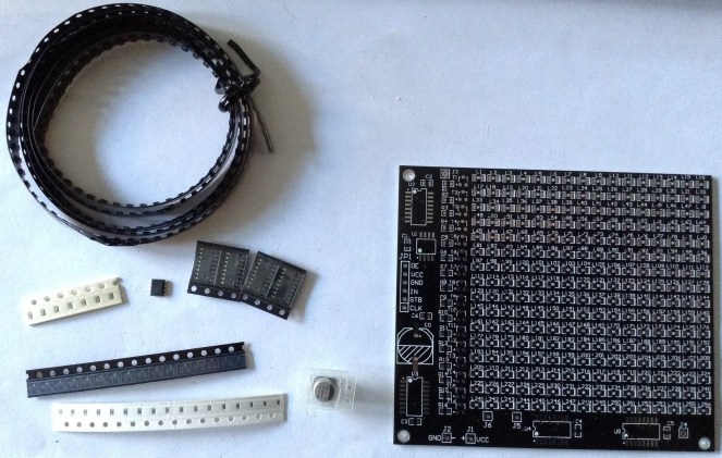
Mini LED Matrix MAX2719 PCB
In the end, rather than mess around with breakouts, I just dived right in and tried to design a PCB that would support a MAX7219 and one of my mini LEDs. I went with the MAX7219 over the HT16K33 as it seemed a simpler choice at this point in time. I had to create a custom symbol for my LED matrix following the pinout as shown previously.
In terms of connecting to the MAX7219, I have the following:
- SEG A – G + DP -> ROWS 1 – 8
- DIG 0 – 7 -> COLS 1 – 8
There was no way I would get a DIP version on – and I did try. One thought was if I had a PCB for several matrices at the same time, then I would have more layout options – but it just wouldn’t go.
So I decided to go with the surface mount version of the MAX7219. This comes in a SOP-24 package which looks just about hand solderable.
I have two board designs – one for two matrices and one for four. My first four-matrix design was a 2×2 square, but I just could not get traces between pins between the two sets of boards, so in the end I went with a 1×4 layout which gives plenty of room between the two long rows of LED matrix pins.
Unfortunately I managed to get the pitch wrong for my LED matrix and the rows are one pin-row-header too wide. But to be honest, I’m not sure I’d have been able to route it with them any narrower, so maybe this is just the way I’ll have to do it!
Each MAX7219 has a 0805 footprint 62K resistor and 100nF capacitor, although when it came to it, I only had 75K resistors in my parts box, so I used those.
There are IN and OUT headers so the idea is that the boards can be chained. I’ll have to see how well that works in practice.
I initially went with standard pin header sockets for the matrix as they can be bent fairly easily, but unfortunately they don’t make very good contact with the pins on the matrix, so I switched to round-hole pin headers instead.
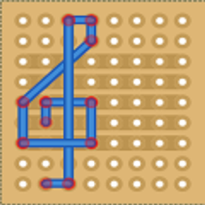
There is another issue with the two-matrix board too. The DOUT signal from the second MAX7219 isn’t connected to the OUT header. This was an oversight on my part in creating the two-matrix board as a cut-down version of the four-matrix board.
To fix this a patch wire is required as follows:
That isn’t a trivial patch, but it’s not impossible either. The four-matrix board should all be connected ok.
Example Code
Driving the displays is relatively straight forward, it is just a case of hooking it up to an Arduino’s SPI and sending a number of addr-data pairs, one for each chained MAX7219, detailing either commands or DIGIT data to be displayed.
There is one problem however.
When it comes to programming the MAX7219, the register address corresponds to a DIGIT, which for me is a “column” value; and the data programmed corresponds to the SEGMENTS to illuminate, which for me is a “row”. Recall the MAX7219 is designed for common cathode 7-segment displays, but I’m using it to drive a common anode LED matrix.
So this means I am scanning columns and setting rows. But as the matrix is rotated through 90 degrees on the circuit board, it appears that I’m scanning rows and setting columns. It gets more confusing…
Mapping to segments, I’ve made a mistake. I thought DP was the last segment, but when it comes to setting the SEGMENT values in the registers for the MAX7219, they are encoded in an 8-bit value as follows:
I’ve hooked them up as follows in the schematic
Which means that to get R8, R7…R1 in the right “column” I need the 8-bit value written to be in the following format:
MAX7219 Register Bit:   7  6  5  4  3  2  1  0
     MAX7219 Segment:  DP  A  B  C  D  E  F  G
    LED Matrix "ROW":  R8 R1 R2 R3 R4 R5 R6 R7
     Physical Column:   1  8  7  6  5  4  3  2
This corresponds to the LED matrix being oriented with pin 1 top left. This makes the top left LED correspond to physical (row 1, column 1) and the bottom right LED is (row 8, column 8).
This means that when creating a bit pattern for the column values, they are swapped compared to bit numbers, and DP needs inserting into bit 7.
val = ((val & 0xff)>>1) | ((val & 0xff)<<7);
It does, ironically, mean that to scan columns in the order left->right, I can simply use:
for (int r=0; r<8; r++) {
  for (int c=0; c<8; c++) {
    // to scan columns 1 to 8
    uint8_t val = (1<<c);
    // adjust for DP
    val = ((val & 0xff)>>1) | ((val & 0xff)<<7);
    // Convert rows 0-7 to register address 1-8
    sendToSPI(r+1, c);
  }
}
It’s quirky, but it works!
But if I stick with this approach, then any bitmaps (or fonts!) stored in memory for display will have to be stored horizontally mirrored.
The final test code for an Arduino Uno or Nano, using the standard SPI pins (13=clock; 11=data out):
#include <SPI.h>
#define SS_PIN 10
#define NUM_MAX7219 2

#define MAX7219_TEST        0x0f
#define MAX7219_BRIGHTNESS  0x0a
#define MAX7219_SCAN_LIMIT  0x0b
#define MAX7219_DECODE_MODE 0x09
#define MAX7219_SHUTDOWN    0x0C

void maxCommand (uint8_t address, uint8_t value) {
  digitalWrite(SS_PIN, LOW);
  for (int i=0; i<NUM_MAX7219; i++) {
    SPI.transfer(address);      // Send address.
    SPI.transfer(value);        // Send the value.
  }
  digitalWrite(SS_PIN, HIGH); // Finish transfer.
}

void maxData (uint8_t row, uint8_t value) {
  digitalWrite(SS_PIN, LOW);
  for (int i=0; i<NUM_MAX7219; i++) {
    SPI.transfer(row+1);        // ROW registers address 1-8
    uint8_t val = value;
    val = ((val & 0xff)>>1) | ((val & 0xff)<<7);
    SPI.transfer(val);     // Send the value.
  }
  digitalWrite(SS_PIN, HIGH); // Finish transfer.
}

void setup() {
  pinMode(SS_PIN, OUTPUT);

  SPI.setBitOrder(MSBFIRST);
  SPI.begin();
  delay(500);

  maxCommand(MAX7219_TEST, 0x01);        // Test mode on
  delay(1000);
  maxCommand(MAX7219_TEST, 0x00);        // Test mode off
  maxCommand(MAX7219_DECODE_MODE, 0x00); // Disable BCD mode.
  maxCommand(MAX7219_BRIGHTNESS, 0x00);  // Turn brightness right down
  maxCommand(MAX7219_SCAN_LIMIT, 0x0f);  // Use all digits
  maxCommand(MAX7219_SHUTDOWN, 0x01);    // Turn on

  // Start with everything off
  for (int r=0; r<8; r++) {
    maxData(r, 0);
  }

  for (int r=0; r<8; r++) {
    maxData(r, 255);
    delay(500);
    maxData(r, 0);
  }

  for (int c=0; c<8; c++) {
    for (int r=0; r<8; r++) {
      maxData(r, (1<<c));
    }
    delay(500);
  }

  for (int r=0; r<8; r++) {
    maxData(r, 0);
  }
}

void loop() {
  for (int r=0; r<8; r++) {
    for (int c=0; c<8; c++) {
      maxData (r, (1<<c));
      delay(200);
    }
    maxData (r, 0);
  }
}
Conclusion
I haven’t published the PCBs as I wasn’t sure many would accept the issues with them, and I didn’t want to spend ages attempting to explain them away in my GitHub repository, but if are of interest, given all the above, ping me a message somehow (via Mastodon is probably easiest) and I can send on Gerbers or KiCad files.
I’d like to get a whole block of 20 or so LED matrices all tied together. I’ll post back here if I manage it.
Software wise, I’ve proved the principle but can’t decide at the moment if it is more intuitive to think of the columns going left to right, or right to left. With hindsight it would have been a lot simpler to map them onto the SEGMENTS already bit-swapped. And with DP in the right place of course.
Summary of the known errors for the board:
- LED matrix footprint too wide.
- Missing DOUT connection on the two-matrix board.
- DP is mapped incorrectly to the columns.
- Ideally all segments would be mapped more usefully to columns.
Still, amazingly, given the above limitations, the PCBs do actually work.
Kevin
https://makertube.net/w/7uPTDhFuALk4SvHrpponXb
#include #ledMatrix


![<div><img alt="" class="attachment-large size-large wp-post-image" height="450" src="https://hackaday.com/wp-content/uploads/2025/02/The-Fibrovisor-4-46-screenshot.png?w=800" style="margin: 0 auto; margin-bottom: 15px;" width="800" /></div><p>If you’ve ever seen those cheap LED fiber optic wands at the dollar store, you’ve probably just thought of them as a simple novelty. However, as [Ancient] shows us, <a href="https://www.youtube.com/watch?v=zz59e1wWyVc" target="_blank">you can turn them into a surprisingly nifty little display</a> if you’re so inclined.</p>
<p>The build starts by removing the fiber optic bundle from the wand. One end is left as a round bundle. At the other end, the strands are then fed into plastic frames to separate them out individually. After plenty of tedious sorting, the fibers are glued in place in a larger rectangular 3D-printed frame, which holds the fibers in place over a matrix of LEDs. The individual LEDs of the matrix light individual fibers, which carry the light to the round end of the bundle. The result is a tiny little round display driven by a much larger one at the other end.</p>
<p>[Ancient] had hoped to use the set up for a volumetric display build, but found it too fragile to be fit for purpose. Still, it’s interesting to look at nonetheless, and a good demonstration of how fiber optics work in practice. As this display shows, you can have two glass fibers carrying completely different wavelengths of light righ](https://files.mastodon.social/cache/media_attachments/files/114/086/203/182/719/169/original/54e16b0cb0d40c65.png)